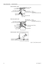
Setup & Operation 3. Environment and Installation
C8 Rev.13
29
3. Environment and Installation
Installation and transportation of robots and robotic equipment shall be performed
by qualified personnel and should conform to all national and local codes.
3.1 Environmental Conditions
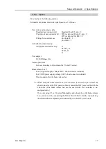
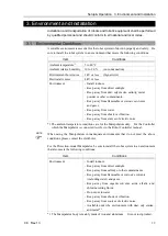
A suitable environment is essential for the robot system to function properly and safely. Be
sure to install the robot system in an environment that meets the following conditions:
Item
Conditions
Ambient temperature
*1
5 to 40
°
C
Ambient relative humidity 10 to
80 %
(no condensation)
First transient burst noise
1 kV or less (Signal wire)
Electrostatic noise
4 kV or less
Environment
- Install indoors.
- Keep away from direct sunlight.
- Keep away from dust, oily smoke, salinity, metal
powder or other contaminants.
- Keep away from flammable or corrosive solvents
and gases.
- Keep away from water.
- Keep away from shock or vibration.
- Keep away from sources of electric noise.
*1 The ambient temperature conditions are for the Manipulators only. For the Controller
which the Manipulator is connected to, refer to the Robot Controller manual.
When using the Manipulators in inadequate environments that do not meet the above
conditions, please contact the distributor.
For the Protection-model Manipulator, be sure to install the robot system in an environment
that also meets the following conditions:
Item
Conditions
Environment
- Install indoors.
- Keep away from direct sunlight.
- Keep away from salinity or other contaminants.
- Keep away from flammable or corrosive solvents
(including water) and gases.
- Keep away from organic solvents, acids, alkalis, and
chlorine cutting fluids.
- Do not use in water.
- Keep away from shock or vibration.
- Keep away from sources of electric noise.
- Available under the environment with dust, oily smoke,
and metal *
2
.
*1 The Manipulator body is mainly made of iron and aluminum. It is not rust-proofed.
NOTE
Summary of Contents for C8 Series
Page 1: ...Rev 13 EM208R4413F 6 Axis Robots C8 series MANIPULATOR MANUAL ...
Page 2: ...Manipulator manual C8 series Rev 13 ...
Page 8: ...vi C8 Rev 13 ...
Page 14: ...Table of Contents xii C8 Rev 13 ...
Page 16: ......
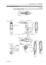
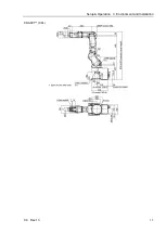
Page 31: ...Setup Operation 2 Specifications C8 Rev 13 17 2 4 Outer Dimensions Unit mm 2 4 1 C8 A701 C8 ...
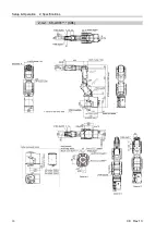
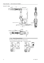
Page 32: ...Setup Operation 2 Specifications 18 C8 Rev 13 2 4 2 C8 A901 C8L ...
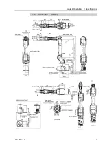
Page 33: ...Setup Operation 2 Specifications C8 Rev 13 19 2 4 3 C8 A1401 C8XL ...
Page 49: ...Setup Operation 3 Environment and Installation C8 Rev 13 35 C8 A901 C8L ...
Page 98: ......
Page 183: ...Maintenance 4 Cable Unit C8 Rev 13 169 4 2 Connector Pin Assignment 4 2 1 Signal Cable ...
Page 184: ...Maintenance 4 Cable Unit 170 C8 Rev 13 ...
Page 185: ...Maintenance 4 Cable Unit C8 Rev 13 171 ...
Page 186: ...Maintenance 4 Cable Unit 172 C8 Rev 13 4 2 2 Power Cable C8 A701 C8 C8 A901 C8L ...
Page 187: ...Maintenance 4 Cable Unit C8 Rev 13 173 C8 A1401 C8XL ...
Page 188: ...Maintenance 4 Cable Unit 174 C8 Rev 13 C8 A701 C8 C8 A901 C8L C8 A1401 C8XL ...


