


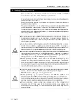


Setup & Operation 6. Options
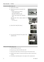
78
C8 Rev.13
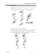
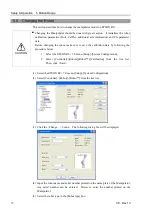
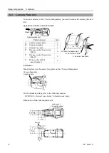
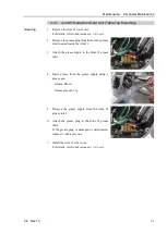
6.2 Camera Plate Unit
To mount a camera to the C8 series Manipulator, you need to mount the camera plate unit
first.
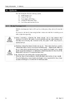
Appearance of arm end with camera
Camera plate unit
Camera
B: Camera mid plate
D
C: Camera base plate
A: Camera adapter plate
E
F
D
D
Parts included
Qty.
A Camera adapter plate
1
B Camera mid plate
1
C Camera base plate
1
D Hexagon socket head screws
M4
×
12
6
E
Hexagon socket head screws
M4
×
20
2
F
Plain washer for M4
(small washer)
2
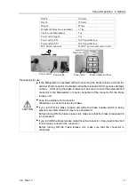
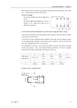
Installation
Mounting holes for the camera base plate on the C8 series Manipulator
Camera base plate
mounting hole
For the installation steps, refer to the following manual:
EPSON RC+ Option Vision Guide 7.0 Hardware & Setup
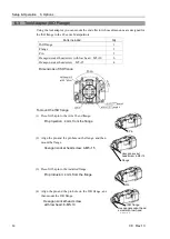
Dimension of the camera plate unit
(for securing cables)
Camera
6×M4 depth 8.5
Summary of Contents for C8 Series
Page 1: ...Rev 13 EM208R4413F 6 Axis Robots C8 series MANIPULATOR MANUAL ...
Page 2: ...Manipulator manual C8 series Rev 13 ...
Page 8: ...vi C8 Rev 13 ...
Page 14: ...Table of Contents xii C8 Rev 13 ...
Page 16: ......
Page 31: ...Setup Operation 2 Specifications C8 Rev 13 17 2 4 Outer Dimensions Unit mm 2 4 1 C8 A701 C8 ...
Page 32: ...Setup Operation 2 Specifications 18 C8 Rev 13 2 4 2 C8 A901 C8L ...
Page 33: ...Setup Operation 2 Specifications C8 Rev 13 19 2 4 3 C8 A1401 C8XL ...
Page 49: ...Setup Operation 3 Environment and Installation C8 Rev 13 35 C8 A901 C8L ...
Page 98: ......
Page 183: ...Maintenance 4 Cable Unit C8 Rev 13 169 4 2 Connector Pin Assignment 4 2 1 Signal Cable ...
Page 184: ...Maintenance 4 Cable Unit 170 C8 Rev 13 ...
Page 185: ...Maintenance 4 Cable Unit C8 Rev 13 171 ...
Page 186: ...Maintenance 4 Cable Unit 172 C8 Rev 13 4 2 2 Power Cable C8 A701 C8 C8 A901 C8L ...
Page 187: ...Maintenance 4 Cable Unit C8 Rev 13 173 C8 A1401 C8XL ...
Page 188: ...Maintenance 4 Cable Unit 174 C8 Rev 13 C8 A701 C8 C8 A901 C8L C8 A1401 C8XL ...