


Maintenance 7. Joint #3
C8 Rev.13
239
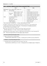
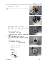
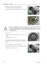
8.
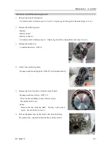
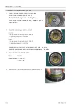
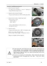
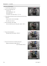
Remove the Joint #3 motor unit.
Be careful not to drop the removed connectors inside the Arm.
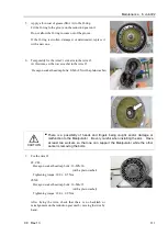
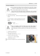
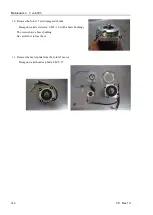
9.
Remove the Joint #3 pulley 1 and the drive boss from the
motor shaft of the Joint #3 motor unit.
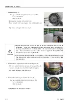
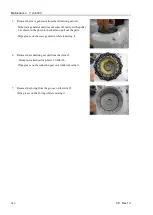
Remove two screws at the flat (D-cut) part of the motor shaft
when viewing from above. (A in the figure)
Pulley and motor shaft screws (A)
Hexagon socket set screws: 2-M5×12
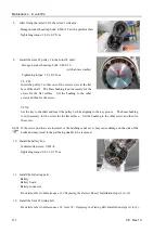
Do not remove the pulley and drive boss screws (B in the
figure.
There is a brass bushing on one of the set screws.
If you removed the screws (B), be careful not to lose the brass
bushing.
Pulley and drive boss screws (B)
Hexagon socket set screws: 2-M5×6
(with a brass bushing)
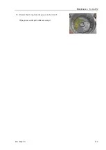
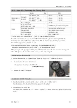
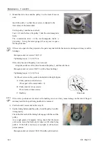
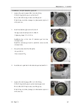
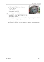
A: Pulley and motor shaft screws
(D-cut part of the motor shaft
×
2)
B: Pulley and drive boss screws
Do not remove these screws.
C: Bushing
Pulley
Drive boss
A
A
C
B
B
NOTE
NOTE
Summary of Contents for C8 Series
Page 1: ...Rev 13 EM208R4413F 6 Axis Robots C8 series MANIPULATOR MANUAL ...
Page 2: ...Manipulator manual C8 series Rev 13 ...
Page 8: ...vi C8 Rev 13 ...
Page 14: ...Table of Contents xii C8 Rev 13 ...
Page 16: ......
Page 31: ...Setup Operation 2 Specifications C8 Rev 13 17 2 4 Outer Dimensions Unit mm 2 4 1 C8 A701 C8 ...
Page 32: ...Setup Operation 2 Specifications 18 C8 Rev 13 2 4 2 C8 A901 C8L ...
Page 33: ...Setup Operation 2 Specifications C8 Rev 13 19 2 4 3 C8 A1401 C8XL ...
Page 49: ...Setup Operation 3 Environment and Installation C8 Rev 13 35 C8 A901 C8L ...
Page 98: ......
Page 183: ...Maintenance 4 Cable Unit C8 Rev 13 169 4 2 Connector Pin Assignment 4 2 1 Signal Cable ...
Page 184: ...Maintenance 4 Cable Unit 170 C8 Rev 13 ...
Page 185: ...Maintenance 4 Cable Unit C8 Rev 13 171 ...
Page 186: ...Maintenance 4 Cable Unit 172 C8 Rev 13 4 2 2 Power Cable C8 A701 C8 C8 A901 C8L ...
Page 187: ...Maintenance 4 Cable Unit C8 Rev 13 173 C8 A1401 C8XL ...
Page 188: ...Maintenance 4 Cable Unit 174 C8 Rev 13 C8 A701 C8 C8 A901 C8L C8 A1401 C8XL ...