Setup & Operation 3. Environment and Installation
32
C8 Rev.13
When condensation occurs on the Manipulator during transport or storage, turn ON the
power only after the condensation dries.
When using the Manipulator for the robot system again after long-term storage, perform a
test run to verify that the Manipulator works properly. Then, operate the Manipulator
thoroughly.
Relocating
Follow the procedures described below when relocating the Manipulator.
(1) Turn OFF the power for all devices and unplug the power cable connector and signal
cable connector from the Controller.
Do not unplug the M/C cable (power cable and signal cable) from the Manipulator.
(M/C cable 3 m: 2 kg)
Remove the mechanical stops if using them to limit the motion range.
For details on the motion range, refer to the
Setup & Operation 5.2 Motion Range
Setting by Mechanical Stops
.
(2) Unscrew the anchor bolts. Then, remove the Manipulator from the base table.
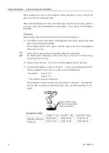
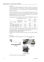
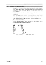
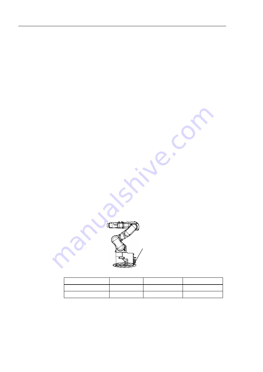
(3) Position the Manipulator as shown in the figure. Then, secure the Manipulator to the
delivery equipment or have at least 2 people to carry the Manipulator.
Recommend: Joint #2 +55
°
Joint #3
−
55
°
* The posture is common to all models.
Do not hold the bottom of the base (the screened parts in the figure). Holding these
parts by hand is extremely hazardous and may cause your hands and fingers to be
caught.
Figure: C8-A901* (C8L)
DO NOT hold the bottom
of the base by hand.
Manipulator weight
C8-A701***: C8
C8-A901***: C8L
C8-A1401***: C8XL
Standard, Cleanroom
49 kg: 108 lbs.
52 kg: 115 lbs.
62 kg: 137 lbs.
Protection
53 kg: 117 lbs.
56 kg: 123 lbs.
66 kg: 146 lbs.
NOTE
Summary of Contents for C8 Series
Page 1: ...Rev 13 EM208R4413F 6 Axis Robots C8 series MANIPULATOR MANUAL ...
Page 2: ...Manipulator manual C8 series Rev 13 ...
Page 8: ...vi C8 Rev 13 ...
Page 14: ...Table of Contents xii C8 Rev 13 ...
Page 16: ......
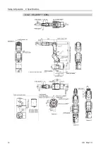
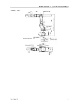
Page 31: ...Setup Operation 2 Specifications C8 Rev 13 17 2 4 Outer Dimensions Unit mm 2 4 1 C8 A701 C8 ...
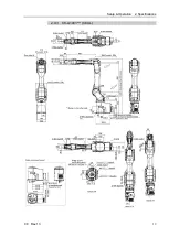
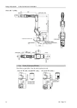
Page 32: ...Setup Operation 2 Specifications 18 C8 Rev 13 2 4 2 C8 A901 C8L ...
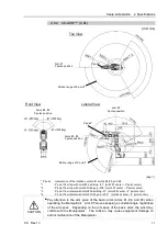
Page 33: ...Setup Operation 2 Specifications C8 Rev 13 19 2 4 3 C8 A1401 C8XL ...
Page 49: ...Setup Operation 3 Environment and Installation C8 Rev 13 35 C8 A901 C8L ...
Page 98: ......
Page 183: ...Maintenance 4 Cable Unit C8 Rev 13 169 4 2 Connector Pin Assignment 4 2 1 Signal Cable ...
Page 184: ...Maintenance 4 Cable Unit 170 C8 Rev 13 ...
Page 185: ...Maintenance 4 Cable Unit C8 Rev 13 171 ...
Page 186: ...Maintenance 4 Cable Unit 172 C8 Rev 13 4 2 2 Power Cable C8 A701 C8 C8 A901 C8L ...
Page 187: ...Maintenance 4 Cable Unit C8 Rev 13 173 C8 A1401 C8XL ...
Page 188: ...Maintenance 4 Cable Unit 174 C8 Rev 13 C8 A701 C8 C8 A901 C8L C8 A1401 C8XL ...

