Maintenance 16. Calibration
C8 Rev.13
325
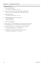
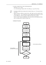
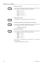
After resetting the error, the motor encoder of the joint whose parts have been
replaced will be initialized.
Set the jog mode to “Joint” in [Jog & Teach] and operate the Manipulator in jog
motion to match the home position marks (0 pulse position) of the joint accurately.
When the joint cannot move to the home position, operate the Manipulator to
match the tram mark placed in
Setup & Operation 3.7 Checking the Basic
Orientation
as accurate as possible.
Initialize the encoder when the joint matches the home position or the tram mark.
For the encoder initialization, refer to the procedure indicated above.
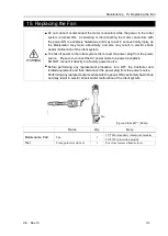
When the origin of the Joint #5 is calibrated, the Joint #6 will be out of position.
(Due to the structure of the Manipulator, any offset in the position of the Joint #5
affects the Joint #6.)
Calibrate the origin of the Joint #6 together when calibrating the Joint #5.
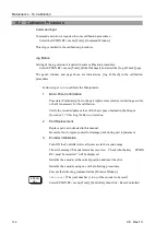
4. Calibration
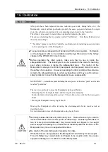
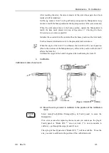
Calibration marks of each joint
(Figure: C8-A1401** (C8XL))
EPSON
RC+
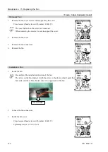
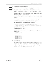
4-1 Move the arm you want to calibrate to the position of the calibration
mark.
Select menu-[Tool]-[Robot Manager]-[Jog & Teach] panel to move the
Manipulator.
If an error occurs after replacing the motor and you cannot use the [Jog &
Teach] panel or “Brake OFF, *” does not work (* is an axis number to
calibrate.), go through the steps (4) and (5) now.
Then, [Jog & Teach] panel and “Brake OFF, *” will be available. Move the
arm you want to calibrate to the position of the calibration mark.
NOTE
Summary of Contents for C8 Series
Page 1: ...Rev 13 EM208R4413F 6 Axis Robots C8 series MANIPULATOR MANUAL ...
Page 2: ...Manipulator manual C8 series Rev 13 ...
Page 8: ...vi C8 Rev 13 ...
Page 14: ...Table of Contents xii C8 Rev 13 ...
Page 16: ......
Page 31: ...Setup Operation 2 Specifications C8 Rev 13 17 2 4 Outer Dimensions Unit mm 2 4 1 C8 A701 C8 ...
Page 32: ...Setup Operation 2 Specifications 18 C8 Rev 13 2 4 2 C8 A901 C8L ...
Page 33: ...Setup Operation 2 Specifications C8 Rev 13 19 2 4 3 C8 A1401 C8XL ...
Page 49: ...Setup Operation 3 Environment and Installation C8 Rev 13 35 C8 A901 C8L ...
Page 98: ......
Page 183: ...Maintenance 4 Cable Unit C8 Rev 13 169 4 2 Connector Pin Assignment 4 2 1 Signal Cable ...
Page 184: ...Maintenance 4 Cable Unit 170 C8 Rev 13 ...
Page 185: ...Maintenance 4 Cable Unit C8 Rev 13 171 ...
Page 186: ...Maintenance 4 Cable Unit 172 C8 Rev 13 4 2 2 Power Cable C8 A701 C8 C8 A901 C8L ...
Page 187: ...Maintenance 4 Cable Unit C8 Rev 13 173 C8 A1401 C8XL ...
Page 188: ...Maintenance 4 Cable Unit 174 C8 Rev 13 C8 A701 C8 C8 A901 C8L C8 A1401 C8XL ...


