


Maintenance 3. Covers
130
C8 Rev.13
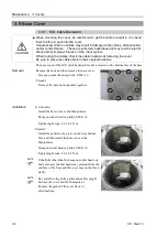
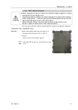
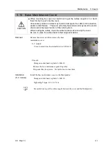
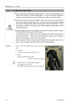
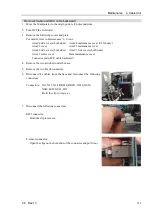
3.12 Connector Sub Plate
CAUTION
■
Do not remove the connector sub plate forcibly. It may result in damage to the
cables, disconnection, and/or contact failure. These are extremely hazardous
and may result in electric shock and/or improper function of the robot system.
■
When removing the connector sub plate, make sure to remove all connectors of
the connector plate and the M/C cable. Removing only the connector sub plate
may result in damage to the cables, disconnection, and/or contact failure. These
are extremely hazardous and may result in electric shock and/or improper function
of the robot system.
■
When installing the connector sub plate, be careful not to get the cables caught in
it or bend them forcibly to push into the cover.
Unnecessary strain on cables may result in damage to the cables, disconnection,
and/or contact failure. These are extremely hazardous and may result in electric
shock and/or improper function of the robot system.
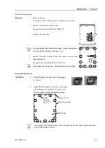
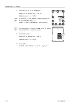
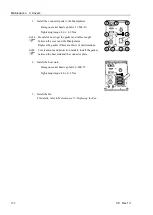
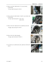
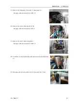
When routing the cables, check the cable locations at removing the connector sub
plate. Be sure to place the cables back to their original locations.
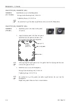
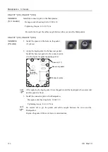
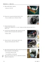
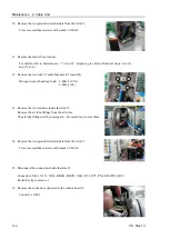
Removal
Remove the bolts and then remove the connector sub
plate.
S, C models:
Hexagon socket head cap bolts: 4-M4×10
P model:
Hexagon socket head cap bolts:
4-M4×10 (with a seal washer)
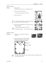
Remove the base sub plate gasket together.
The gasket has the spacers.
Be careful not to lose the seal washers and spacers.
NOTE
Summary of Contents for C8 Series
Page 1: ...Rev 13 EM208R4413F 6 Axis Robots C8 series MANIPULATOR MANUAL ...
Page 2: ...Manipulator manual C8 series Rev 13 ...
Page 8: ...vi C8 Rev 13 ...
Page 14: ...Table of Contents xii C8 Rev 13 ...
Page 16: ......
Page 31: ...Setup Operation 2 Specifications C8 Rev 13 17 2 4 Outer Dimensions Unit mm 2 4 1 C8 A701 C8 ...
Page 32: ...Setup Operation 2 Specifications 18 C8 Rev 13 2 4 2 C8 A901 C8L ...
Page 33: ...Setup Operation 2 Specifications C8 Rev 13 19 2 4 3 C8 A1401 C8XL ...
Page 49: ...Setup Operation 3 Environment and Installation C8 Rev 13 35 C8 A901 C8L ...
Page 98: ......
Page 183: ...Maintenance 4 Cable Unit C8 Rev 13 169 4 2 Connector Pin Assignment 4 2 1 Signal Cable ...
Page 184: ...Maintenance 4 Cable Unit 170 C8 Rev 13 ...
Page 185: ...Maintenance 4 Cable Unit C8 Rev 13 171 ...
Page 186: ...Maintenance 4 Cable Unit 172 C8 Rev 13 4 2 2 Power Cable C8 A701 C8 C8 A901 C8L ...
Page 187: ...Maintenance 4 Cable Unit C8 Rev 13 173 C8 A1401 C8XL ...
Page 188: ...Maintenance 4 Cable Unit 174 C8 Rev 13 C8 A701 C8 C8 A901 C8L C8 A1401 C8XL ...