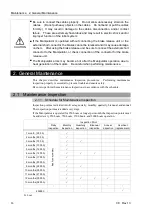


Maintenance 2. General Maintenance
100
C8 Rev.13
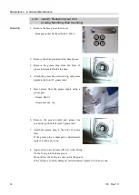
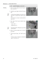
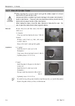
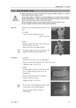
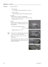
2.3.8 Joint #6 Bevel Gear
Greasing
1.
Remove the Arm #5 grease inlet cover.
Hexagon socket head cap bolts: 4-M3
×
6
2.
Remove the O-ring located in the base groove.
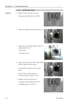
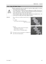
3.
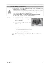
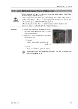
Apply grease to the mating surface of the bevel
gear inside the Arm #5.
Grease: SK-2
Grease amount: 2g
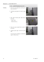
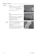
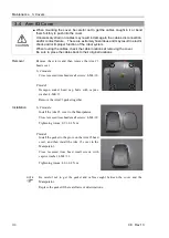
4.
Apply a thin coat of grease (SK-2) to the O-ring.
Fit the O-ring into the base groove.
Do not allow the O-ring to come out of the
groove.
If the O-ring is swollen, damaged, or
deteriorated, replace it with a new one.
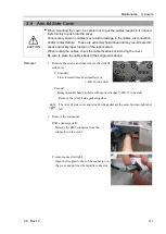
5.
Install the Arm #5 grease inlet cover.
Hexagon socket head cap bolts: 4-M3
×
6
Tightening torque: 2.0
±
0.1 N·m
Summary of Contents for C8 Series
Page 1: ...Rev 13 EM208R4413F 6 Axis Robots C8 series MANIPULATOR MANUAL ...
Page 2: ...Manipulator manual C8 series Rev 13 ...
Page 8: ...vi C8 Rev 13 ...
Page 14: ...Table of Contents xii C8 Rev 13 ...
Page 16: ......
Page 31: ...Setup Operation 2 Specifications C8 Rev 13 17 2 4 Outer Dimensions Unit mm 2 4 1 C8 A701 C8 ...
Page 32: ...Setup Operation 2 Specifications 18 C8 Rev 13 2 4 2 C8 A901 C8L ...
Page 33: ...Setup Operation 2 Specifications C8 Rev 13 19 2 4 3 C8 A1401 C8XL ...
Page 49: ...Setup Operation 3 Environment and Installation C8 Rev 13 35 C8 A901 C8L ...
Page 98: ......
Page 183: ...Maintenance 4 Cable Unit C8 Rev 13 169 4 2 Connector Pin Assignment 4 2 1 Signal Cable ...
Page 184: ...Maintenance 4 Cable Unit 170 C8 Rev 13 ...
Page 185: ...Maintenance 4 Cable Unit C8 Rev 13 171 ...
Page 186: ...Maintenance 4 Cable Unit 172 C8 Rev 13 4 2 2 Power Cable C8 A701 C8 C8 A901 C8L ...
Page 187: ...Maintenance 4 Cable Unit C8 Rev 13 173 C8 A1401 C8XL ...
Page 188: ...Maintenance 4 Cable Unit 174 C8 Rev 13 C8 A701 C8 C8 A901 C8L C8 A1401 C8XL ...