


Setup & Operation 4. End Effectors
54
C8 Rev.13
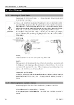
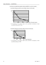
4.3.2 INERTIA setting
Inertia Moment and the INERTIA Setting
The inertia moment is defined as “the ratio of the torque applied to a rigid body and its
resistance to motion”. This value is typically referred to as “the moment of inertia”,
“inertia”, or “GD
2
”. When the Manipulator operates with objects such as an end effector
attached to the Arm #6, the moment of inertia of load must be considered.
CAUTION
■
The inertia moment of the load (weight of the end effector and work piece) must
be 0.15 kg·m
2
or less. The C8 series Manipulators are not designed to work with
inertia moment exceeding 0.15 kg·m
2
.
Always set the inertia moment (INERTIA) parameter according to the inertia
moment. Setting a value that is smaller than the actual inertia moment may
cause errors, excessive shock, insufficient function of the Manipulator, and/or
shorten the life of parts/mechanisms.
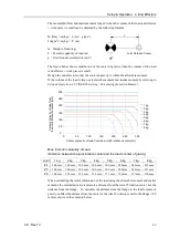
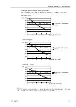
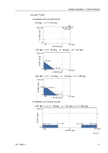
The acceptable inertia moment of load for C8 series Manipulators is 0.03 kg
m
2
nominal
rating and 0.15 kg
m
2
maximum. Change the setting of the inertia moment according to
the inertia moment of the load using the INERTIA command. After the setting has been
changed, the maximum acceleration/deceleration speed of Arm #6 responding to “inertia
moment” is set automatically.
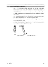
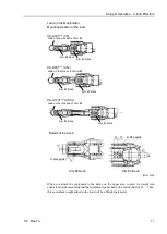
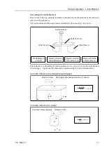
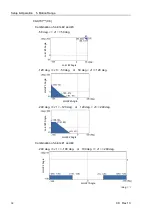
Inertia moment of load on Arm #6
The inertia moment of the load (weight of the end effector and work piece) on the Arm #6
can be set by the “inertia moment (INERTIA)” parameter of the INERTIA command.
EPSON
RC+
Select [Tools]–[Robot Manager]-[Inertia] panel and enter the value in [Load inertia:].
You may also execute the Inertia command from [Command Window].
Summary of Contents for C8 Series
Page 1: ...Rev 13 EM208R4413F 6 Axis Robots C8 series MANIPULATOR MANUAL ...
Page 2: ...Manipulator manual C8 series Rev 13 ...
Page 8: ...vi C8 Rev 13 ...
Page 14: ...Table of Contents xii C8 Rev 13 ...
Page 16: ......
Page 31: ...Setup Operation 2 Specifications C8 Rev 13 17 2 4 Outer Dimensions Unit mm 2 4 1 C8 A701 C8 ...
Page 32: ...Setup Operation 2 Specifications 18 C8 Rev 13 2 4 2 C8 A901 C8L ...
Page 33: ...Setup Operation 2 Specifications C8 Rev 13 19 2 4 3 C8 A1401 C8XL ...
Page 49: ...Setup Operation 3 Environment and Installation C8 Rev 13 35 C8 A901 C8L ...
Page 98: ......
Page 183: ...Maintenance 4 Cable Unit C8 Rev 13 169 4 2 Connector Pin Assignment 4 2 1 Signal Cable ...
Page 184: ...Maintenance 4 Cable Unit 170 C8 Rev 13 ...
Page 185: ...Maintenance 4 Cable Unit C8 Rev 13 171 ...
Page 186: ...Maintenance 4 Cable Unit 172 C8 Rev 13 4 2 2 Power Cable C8 A701 C8 C8 A901 C8L ...
Page 187: ...Maintenance 4 Cable Unit C8 Rev 13 173 C8 A1401 C8XL ...
Page 188: ...Maintenance 4 Cable Unit 174 C8 Rev 13 C8 A701 C8 C8 A901 C8L C8 A1401 C8XL ...