


Setup & Operation 4. End Effectors
C8 Rev.13
49
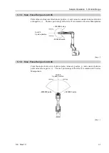
The moment M (Nm) and inertia moment I (kgm
2
) when the volume of the load (end effector
+ work piece) is small can be obtained by the following formula.
M (Nm) = m(kg) × L (m) × g (m/s
2
)
I (kgm
2
) = m(kg) × L
2
(m)
m : Weight of load (kg)
L : Eccentric quantity of load (m)
g : Gravitational acceleration (m/s
2
)
T
L
Joint Rotation Center
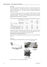
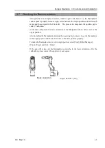
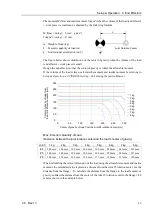
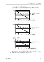
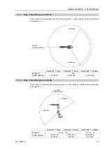
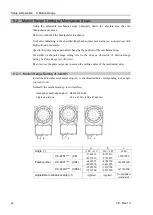
The figure below shows distribution of the center of gravity when the volume of the load
(end ef work piece) is small.
Design the end effector so that the center of gravity is within the allowable moment.
If the volume of the load is large, calculate the moment and inertia moment by referring to
Setup & Operation 4.3.2 INERTIA setting - Calculating the Inertia Moment
.
Center of gravity of load from the Arm #5 rotation center [mm]
C
ent
er
of
gr
av
ity
of
load f
rom
the A
rm
#6
rot
at
ion
c
ent
er
[mm]
300
250
200
150
100
50
0
0
50
100
150
200
250
300
1 kg
2 kg
3 kg
4 kg
5 kg
6 kg
7 kg
8 kg
Max. Eccentric Quantity of Load
(Distance between the joint rotation center and the load’s center of gravity)
Joint
1 kg
2 kg
3 kg
4 kg
5 kg
6 kg
7 kg
8 kg
#4
300 mm 300 mm 300 mm 300 mm 300 mm 280 mm 242 mm 212 mm
#5
300 mm 300 mm 300 mm 300 mm 300 mm 280 mm 242 mm 212 mm
#6
300 mm 274 mm 224 mm 194 mm 173 mm 158 mm 137 mm 120 mm
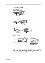
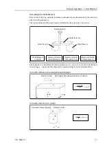
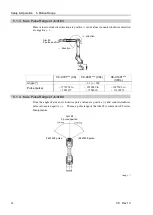
When calculating the critical dimension of the load using the allowable moment and inertia
moment, the calculated value represents a distance from the Arm #5 rotation center, not the
distance from the flange. To calculate the distance from the flange to the load’s center of
gravity, subtract the distance from the center of the Arm #5 rotation center to the flange (=80
mm) as shown in the example below.
Summary of Contents for C8 Series
Page 1: ...Rev 13 EM208R4413F 6 Axis Robots C8 series MANIPULATOR MANUAL ...
Page 2: ...Manipulator manual C8 series Rev 13 ...
Page 8: ...vi C8 Rev 13 ...
Page 14: ...Table of Contents xii C8 Rev 13 ...
Page 16: ......
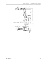
Page 31: ...Setup Operation 2 Specifications C8 Rev 13 17 2 4 Outer Dimensions Unit mm 2 4 1 C8 A701 C8 ...
Page 32: ...Setup Operation 2 Specifications 18 C8 Rev 13 2 4 2 C8 A901 C8L ...
Page 33: ...Setup Operation 2 Specifications C8 Rev 13 19 2 4 3 C8 A1401 C8XL ...
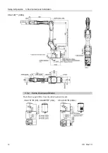
Page 49: ...Setup Operation 3 Environment and Installation C8 Rev 13 35 C8 A901 C8L ...
Page 98: ......
Page 183: ...Maintenance 4 Cable Unit C8 Rev 13 169 4 2 Connector Pin Assignment 4 2 1 Signal Cable ...
Page 184: ...Maintenance 4 Cable Unit 170 C8 Rev 13 ...
Page 185: ...Maintenance 4 Cable Unit C8 Rev 13 171 ...
Page 186: ...Maintenance 4 Cable Unit 172 C8 Rev 13 4 2 2 Power Cable C8 A701 C8 C8 A901 C8L ...
Page 187: ...Maintenance 4 Cable Unit C8 Rev 13 173 C8 A1401 C8XL ...
Page 188: ...Maintenance 4 Cable Unit 174 C8 Rev 13 C8 A701 C8 C8 A901 C8L C8 A1401 C8XL ...