

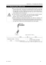


Maintenance 15. Replacing the Fan
320
C8 Rev.13
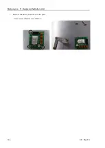
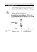
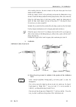
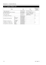
(Figure: Cable backward model)
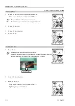
Removal: Fan
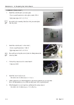
1.
Remove the fan cover screws while supporting the cover.
Cross recessed head screws with washer: 4-M4×35
The cover falls when the screws are removed.
When removing the screws, be sure to support the cover.
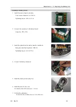
2.
Remove the fan cover.
3.
Remove the fan connectors.
4.
Remove the fan.
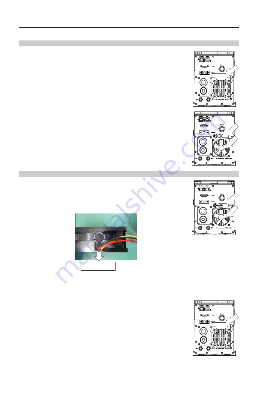
Installation: Fan
1.
Install the fan.
Be careful of the installation direction of the fan.
The arrow on the fan (indicated with the arrow in the photo) should point the
heat sink, and the cables should come to the upper side of the fan.
Heat sink side
2.
Connect the fan connectors.
3.
Install the fan cover.
Cross recessed head screws with washer: 4-M4×35
Tightening torque: 0.9
±
0.1 N·m
NOTE
NOTE
Summary of Contents for C8 Series
Page 1: ...Rev 13 EM208R4413F 6 Axis Robots C8 series MANIPULATOR MANUAL ...
Page 2: ...Manipulator manual C8 series Rev 13 ...
Page 8: ...vi C8 Rev 13 ...
Page 14: ...Table of Contents xii C8 Rev 13 ...
Page 16: ......
Page 31: ...Setup Operation 2 Specifications C8 Rev 13 17 2 4 Outer Dimensions Unit mm 2 4 1 C8 A701 C8 ...
Page 32: ...Setup Operation 2 Specifications 18 C8 Rev 13 2 4 2 C8 A901 C8L ...
Page 33: ...Setup Operation 2 Specifications C8 Rev 13 19 2 4 3 C8 A1401 C8XL ...
Page 49: ...Setup Operation 3 Environment and Installation C8 Rev 13 35 C8 A901 C8L ...
Page 98: ......
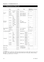
Page 183: ...Maintenance 4 Cable Unit C8 Rev 13 169 4 2 Connector Pin Assignment 4 2 1 Signal Cable ...
Page 184: ...Maintenance 4 Cable Unit 170 C8 Rev 13 ...
Page 185: ...Maintenance 4 Cable Unit C8 Rev 13 171 ...
Page 186: ...Maintenance 4 Cable Unit 172 C8 Rev 13 4 2 2 Power Cable C8 A701 C8 C8 A901 C8L ...
Page 187: ...Maintenance 4 Cable Unit C8 Rev 13 173 C8 A1401 C8XL ...
Page 188: ...Maintenance 4 Cable Unit 174 C8 Rev 13 C8 A701 C8 C8 A901 C8L C8 A1401 C8XL ...