Setup & Operation 5. Motion Range
60
C8 Rev.13
5. Motion Range
WARNING
■
When limiting the motion range for safety, be sure to set by both the pulse range
and mechanical stops. Failure to do so may cause serious safety problems.
The motion range is preset at the factory as describes in the
Setup & Operation 2.5
Standard
Motion Range
. This is the maximum motion range of the Manipulator.
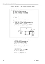
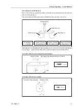
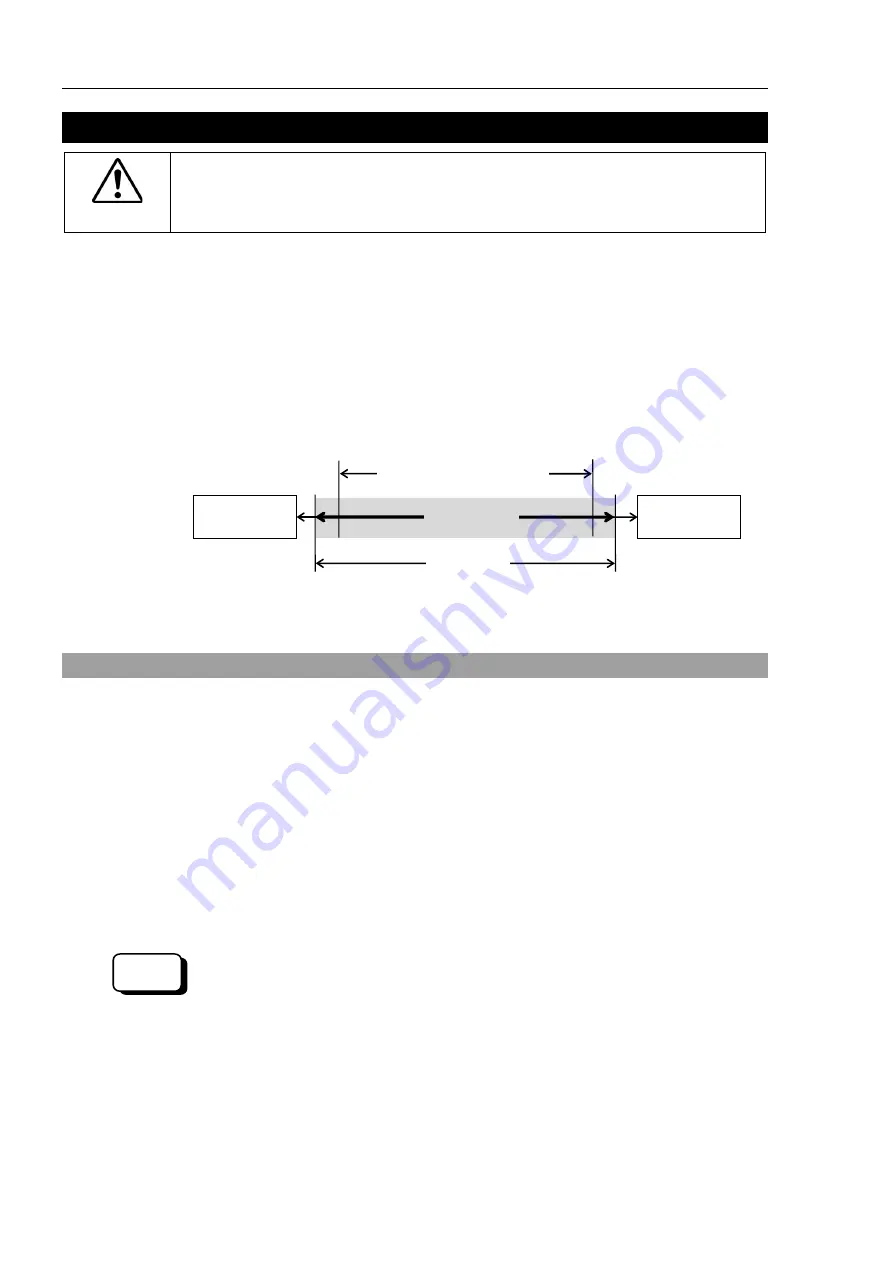
Motion range is set by the following three methods:
1. Setting by pulse range (for all arms)
2. Setting by mechanical stops
3. Setting the Cartesian (rectangular) range in the X, Y coordinate system of the
Manipulator
Mechanical
Stop
Rectangular Range Setting
Pulse Range
Motion Range
Mechanical
Stop
When the motion range is changed due to layout efficiency or safety, follow the descriptions
in
5.1
through
5.4
to set the range.
5.1 Motion Range Setting by Pulse Range (for Each Joint)
Pulses are the basic unit of Manipulator motion. The motion range of the Manipulator is
controlled by the pulse range (the lower limit and the upper limit) of each axis.
Pulse values are read from the encoder output of the servo motor.
The pulse range should be set within the mechanical stop range.
The Arm #1 and #4 do not have a mechanical stop.
Once the Manipulator receives an operating command, it checks whether the target position
specified by the command is within the pulse range before operating. If the target position
is out of the set pulse range, an error occurs and the Manipulator does not move.
EPSON
RC+
The pulse range can be set in [Tools]-[Robot manager]-[Range] panel.
You may also execute the Range command from the [Command Window].
NOTE
NOTE
Summary of Contents for C8 Series
Page 1: ...Rev 13 EM208R4413F 6 Axis Robots C8 series MANIPULATOR MANUAL ...
Page 2: ...Manipulator manual C8 series Rev 13 ...
Page 8: ...vi C8 Rev 13 ...
Page 14: ...Table of Contents xii C8 Rev 13 ...
Page 16: ......
Page 31: ...Setup Operation 2 Specifications C8 Rev 13 17 2 4 Outer Dimensions Unit mm 2 4 1 C8 A701 C8 ...
Page 32: ...Setup Operation 2 Specifications 18 C8 Rev 13 2 4 2 C8 A901 C8L ...
Page 33: ...Setup Operation 2 Specifications C8 Rev 13 19 2 4 3 C8 A1401 C8XL ...
Page 49: ...Setup Operation 3 Environment and Installation C8 Rev 13 35 C8 A901 C8L ...
Page 98: ......
Page 183: ...Maintenance 4 Cable Unit C8 Rev 13 169 4 2 Connector Pin Assignment 4 2 1 Signal Cable ...
Page 184: ...Maintenance 4 Cable Unit 170 C8 Rev 13 ...
Page 185: ...Maintenance 4 Cable Unit C8 Rev 13 171 ...
Page 186: ...Maintenance 4 Cable Unit 172 C8 Rev 13 4 2 2 Power Cable C8 A701 C8 C8 A901 C8L ...
Page 187: ...Maintenance 4 Cable Unit C8 Rev 13 173 C8 A1401 C8XL ...
Page 188: ...Maintenance 4 Cable Unit 174 C8 Rev 13 C8 A701 C8 C8 A901 C8L C8 A1401 C8XL ...

