


Maintenance 8. Joint #4
254
C8 Rev.13
Removal: Joint #4 Motor
1.
Turn OFF the Controller power.
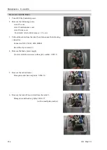
2.
Remove the following covers.
Arm #3 cover
Arm #3 maintenance cover
Arm #2 side cover
For details, refer to
Maintenance: 3. Covers.
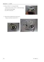
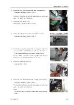
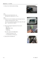
3.
Pull out the cables from the Arm #3 and disconnect the following
connectors.
Connector: X141, X041, BT4, BR041
(Hold the clip to remove.)
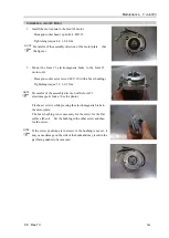
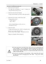
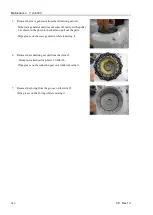
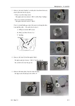
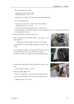
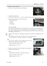
4.
Remove the brake power supply.
Cross recessed head screws with captive washer: 2-M3×6
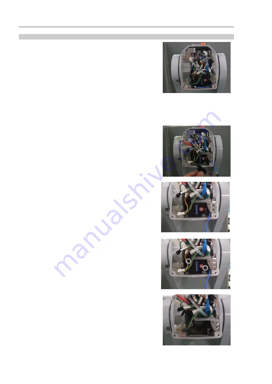
5.
Remove the cable bracket.
Hexagon socket head cap bolts: 2-M4×10
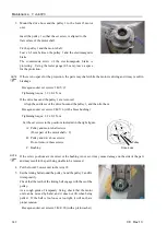
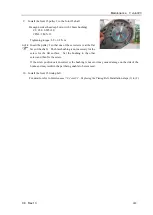
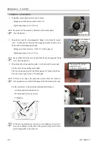
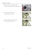
6.
Remove the Joint #4 motor unit from the Arm #3.
Hexagon socket head cap bolts: 2-M4×15
(with a small plain washer)
Summary of Contents for C8 Series
Page 1: ...Rev 13 EM208R4413F 6 Axis Robots C8 series MANIPULATOR MANUAL ...
Page 2: ...Manipulator manual C8 series Rev 13 ...
Page 8: ...vi C8 Rev 13 ...
Page 14: ...Table of Contents xii C8 Rev 13 ...
Page 16: ......
Page 31: ...Setup Operation 2 Specifications C8 Rev 13 17 2 4 Outer Dimensions Unit mm 2 4 1 C8 A701 C8 ...
Page 32: ...Setup Operation 2 Specifications 18 C8 Rev 13 2 4 2 C8 A901 C8L ...
Page 33: ...Setup Operation 2 Specifications C8 Rev 13 19 2 4 3 C8 A1401 C8XL ...
Page 49: ...Setup Operation 3 Environment and Installation C8 Rev 13 35 C8 A901 C8L ...
Page 98: ......
Page 183: ...Maintenance 4 Cable Unit C8 Rev 13 169 4 2 Connector Pin Assignment 4 2 1 Signal Cable ...
Page 184: ...Maintenance 4 Cable Unit 170 C8 Rev 13 ...
Page 185: ...Maintenance 4 Cable Unit C8 Rev 13 171 ...
Page 186: ...Maintenance 4 Cable Unit 172 C8 Rev 13 4 2 2 Power Cable C8 A701 C8 C8 A901 C8L ...
Page 187: ...Maintenance 4 Cable Unit C8 Rev 13 173 C8 A1401 C8XL ...
Page 188: ...Maintenance 4 Cable Unit 174 C8 Rev 13 C8 A701 C8 C8 A901 C8L C8 A1401 C8XL ...