Table of Contents
x
C8 Rev.13
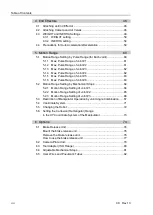
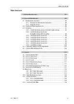
4. Cable Unit
132
4.1 Replacing the Cable Unit ................................................................... 132
4.1.1 Replacing the Cable Unit (M/C Cable Backward) .................. 134
4.1.2 Replacing the Cable Unit (M/C Cable Downward) ................ 164
4.2 Connector Pin Assignment ................................................................. 169
4.2.1 Signal Cable ........................................................................... 169
4.2.2 Power Cable ........................................................................... 172
4.2.3 User Cable ............................................................................. 175
4.2.4 Color of Cables....................................................................... 175
5. Joint #1
176
5.1 M/C Cable Backward (Joint #1) ......................................................... 177
5.1.1 Joint #1 - Replacing the Motor (M/C Cable Backward) ......... 177
5.1.2 Joint #1 - Replacing the Reduction Gear Unit
(M/C Cable Backward) ............................................................ 185
5.1.3 Joint #1 - Replacing the Timing Belt (M/C Cable Backward) . 192
5.1.4 Joint #1 - Replacing the Electromagnetic Brake
(M/C Cable Backward) ............................................................ 199
5.2 M/C Cable Downward (Joint #1) ........................................................ 201
5.2.1 Joint #1 - Replacing the Motor (M/C Cable Downward) ........ 201
5.2.2 Joint #1 - Replacing the Reduction Gear Unit
(M/C Cable Downward) ........................................................... 205
5.2.3 Joint #1 - Replacing the Timing Belt (M/C Cable Downward) 208
5.2.4 Joint #1 - Replacing the Electromagnetic Brake
(M/C Cable Downward) ........................................................... 213
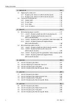
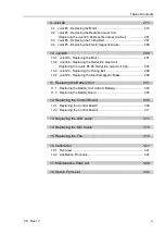
6. Joint #2
216
6.1 Joint #2 - Replacing the Motor ........................................................... 217
6.2 Joint #2- Replacing the Reduction Gear Unit .................................... 226
6.3 Joint #2 - Replacing the Timing Belt .................................................. 233
6.4 Joint #2 - Replacing the Electromagnetic Brake................................ 234
7. Joint #3
235
7.1 Joint #3 - Replacing the Motor ........................................................... 236
7.2 Joint #3 - Replacing the Reduction Gear Unit ................................... 244
7.3 Joint #3 - Replacing the Timing Belt .................................................. 250
7.4 Joint #3 - Replacing the Electromagnetic Brake................................ 251
8. Joint #4
252
8.1 Joint #4 - Replacing the Motor ........................................................... 253
8.2 Joint #4 - Replacing the Reduction Gear Unit ................................... 259
8.3 Joint #4 - Replacing the Timing Belt .................................................. 266
8.4 Joint #4 - Replacing the Electromagnetic Brake................................ 272
Summary of Contents for C8 Series
Page 1: ...Rev 13 EM208R4413F 6 Axis Robots C8 series MANIPULATOR MANUAL ...
Page 2: ...Manipulator manual C8 series Rev 13 ...
Page 8: ...vi C8 Rev 13 ...
Page 14: ...Table of Contents xii C8 Rev 13 ...
Page 16: ......
Page 31: ...Setup Operation 2 Specifications C8 Rev 13 17 2 4 Outer Dimensions Unit mm 2 4 1 C8 A701 C8 ...
Page 32: ...Setup Operation 2 Specifications 18 C8 Rev 13 2 4 2 C8 A901 C8L ...
Page 33: ...Setup Operation 2 Specifications C8 Rev 13 19 2 4 3 C8 A1401 C8XL ...
Page 49: ...Setup Operation 3 Environment and Installation C8 Rev 13 35 C8 A901 C8L ...
Page 98: ......
Page 183: ...Maintenance 4 Cable Unit C8 Rev 13 169 4 2 Connector Pin Assignment 4 2 1 Signal Cable ...
Page 184: ...Maintenance 4 Cable Unit 170 C8 Rev 13 ...
Page 185: ...Maintenance 4 Cable Unit C8 Rev 13 171 ...
Page 186: ...Maintenance 4 Cable Unit 172 C8 Rev 13 4 2 2 Power Cable C8 A701 C8 C8 A901 C8L ...
Page 187: ...Maintenance 4 Cable Unit C8 Rev 13 173 C8 A1401 C8XL ...
Page 188: ...Maintenance 4 Cable Unit 174 C8 Rev 13 C8 A701 C8 C8 A901 C8L C8 A1401 C8XL ...

