Setup & Operation 3. Environment and Installation
30
C8 Rev.13
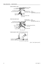
Do not use the Manipulator under conditions where it can be exposed to water or any
other corrosive liquid (including water).
*2 Any contaminants that can deteriorate sealing performance of nitrile rubber oil sealing,
O-rings, packing seals and liquid gasket should be avoided.
Special Environmental Conditions
The protective seals are attached on the Protection-model Manipulator to prevent dust, water,
etc. from the outside. Follow the precautions in use environment described below:
The surface of the Manipulator has general oil resistance. However, if your requirements
specify that the Manipulator must withstand certain kinds of oil, please the supplier of your
region.
Rapid change in temperature and humidity can cause condensation inside the Manipulator.
If your requirements specify that the Manipulator handles food, please the supplier of your
region to check whether the Manipulator will damage the food or not.
The Manipulator cannot be used in corrosive environments where acid or alkaline is used.
In a salty environment where the rust is likely to gather, the Manipulator is susceptible to
rust.
The Controller used with the Protection-model Manipulator does not have protection
features for dusty, wet, or oily environment. The Controller must be placed in an
environment that meets the specified conditions.
WARNING
■
Use an earth leakage breaker on the AC power cable of the Controller to avoid
the electric shock and circuit breakdown caused by an unexpected water leak.
Prepare the earth leakage breaker that pertains the Controller you are using. For
details, refer to the Robot Controller manual.
CAUTION
■
When cleaning the Manipulator, do not rub it strongly with alcohol or benzene.
It may lose luster on the coated face.
Summary of Contents for C8 Series
Page 1: ...Rev 13 EM208R4413F 6 Axis Robots C8 series MANIPULATOR MANUAL ...
Page 2: ...Manipulator manual C8 series Rev 13 ...
Page 8: ...vi C8 Rev 13 ...
Page 14: ...Table of Contents xii C8 Rev 13 ...
Page 16: ......
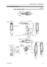
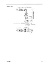
Page 31: ...Setup Operation 2 Specifications C8 Rev 13 17 2 4 Outer Dimensions Unit mm 2 4 1 C8 A701 C8 ...
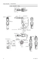
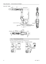
Page 32: ...Setup Operation 2 Specifications 18 C8 Rev 13 2 4 2 C8 A901 C8L ...
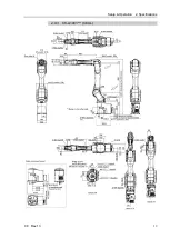
Page 33: ...Setup Operation 2 Specifications C8 Rev 13 19 2 4 3 C8 A1401 C8XL ...
Page 49: ...Setup Operation 3 Environment and Installation C8 Rev 13 35 C8 A901 C8L ...
Page 98: ......
Page 183: ...Maintenance 4 Cable Unit C8 Rev 13 169 4 2 Connector Pin Assignment 4 2 1 Signal Cable ...
Page 184: ...Maintenance 4 Cable Unit 170 C8 Rev 13 ...
Page 185: ...Maintenance 4 Cable Unit C8 Rev 13 171 ...
Page 186: ...Maintenance 4 Cable Unit 172 C8 Rev 13 4 2 2 Power Cable C8 A701 C8 C8 A901 C8L ...
Page 187: ...Maintenance 4 Cable Unit C8 Rev 13 173 C8 A1401 C8XL ...
Page 188: ...Maintenance 4 Cable Unit 174 C8 Rev 13 C8 A701 C8 C8 A901 C8L C8 A1401 C8XL ...

