


Setup & Operation 1. Safety
C8 Rev.13
11
1.7 Warning Labels
The Manipulator has the following warning labels.
The warning labels are attached around the locations where specific dangers exist.
Be sure to comply with descriptions and warnings on the labels to operate and maintain the
Manipulator safely.
Do not tear, damage, or remove the warning labels. Use meticulous care when handling
those parts or units to which the following warning labels are attached as well as the nearby
areas.
Location
Warning Label
NOTE
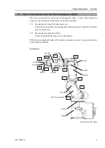
A
To avoid getting hands or fingers
caught, fold the Arm and fix it with a
belt or a similar tool before removing
the base mounting screws.
B
Do not enter the work space when the
Manipulator is operating. It is
extremely hazardous since the Arm
may collide and cause serious safety
problems.
C
Do not touch the current-carrying parts
inside the Manipulator while the power
is ON. It may cause electrical shock.
D
When releasing the brakes, be careful
of the arm falling due to its own
weight.
This warning label is attached on the
Manipulator and optional brake
release box.
When the brake release box is used:
Details of procedures for releasing the
brakes using the brake release box
are described in the Manipulator
manuals.
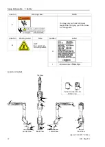
E
Only authorized personnel should
perform sling work and operate a
crane and a forklift. When these
operations are performed by
unauthorized personnel, it is extremely
hazardous and may result in serious
bodily injury and/or severe equipment
damage to the robot system.
Summary of Contents for C8 Series
Page 1: ...Rev 13 EM208R4413F 6 Axis Robots C8 series MANIPULATOR MANUAL ...
Page 2: ...Manipulator manual C8 series Rev 13 ...
Page 8: ...vi C8 Rev 13 ...
Page 14: ...Table of Contents xii C8 Rev 13 ...
Page 16: ......
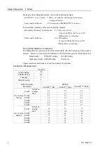
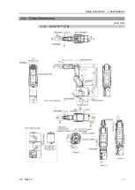
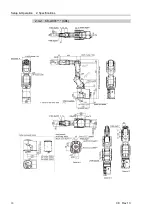
Page 31: ...Setup Operation 2 Specifications C8 Rev 13 17 2 4 Outer Dimensions Unit mm 2 4 1 C8 A701 C8 ...
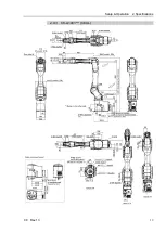
Page 32: ...Setup Operation 2 Specifications 18 C8 Rev 13 2 4 2 C8 A901 C8L ...
Page 33: ...Setup Operation 2 Specifications C8 Rev 13 19 2 4 3 C8 A1401 C8XL ...
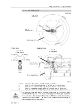
Page 49: ...Setup Operation 3 Environment and Installation C8 Rev 13 35 C8 A901 C8L ...
Page 98: ......
Page 183: ...Maintenance 4 Cable Unit C8 Rev 13 169 4 2 Connector Pin Assignment 4 2 1 Signal Cable ...
Page 184: ...Maintenance 4 Cable Unit 170 C8 Rev 13 ...
Page 185: ...Maintenance 4 Cable Unit C8 Rev 13 171 ...
Page 186: ...Maintenance 4 Cable Unit 172 C8 Rev 13 4 2 2 Power Cable C8 A701 C8 C8 A901 C8L ...
Page 187: ...Maintenance 4 Cable Unit C8 Rev 13 173 C8 A1401 C8XL ...
Page 188: ...Maintenance 4 Cable Unit 174 C8 Rev 13 C8 A701 C8 C8 A901 C8L C8 A1401 C8XL ...


