


Maintenance 4. Cable Unit
C8 Rev.13
151
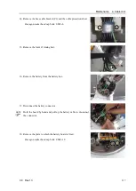
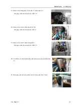
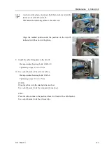
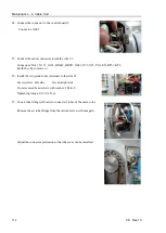
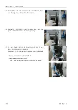
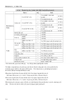
13.
Install the motors for the Joints #5 and #6.
Connect the cables and air tube and store them inside.
Upper photo: Joint #5 motor side
Place the Ethernet cable and the air tube (blue) on the near side.
Lower photo: Joint #6 motor side
Place the other cables and the air tube (clear) on the front side.
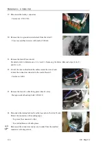
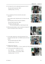
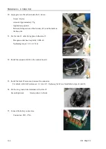
Fix the cables by binding them with a wire tie (INSULOC AB150 or
equivalent) inserted through the hole of the cable fixing plate so that
the cables do not interfere with the Joint #6 motor pulley.
Pay attention so that no connector is installed incorrectly and no cable
is caught between components.
For details, refer to
Maintenance: 9.1 Joint #5 - Replacing the Motor,
Installation steps (4) to (8),
and
Maintenance: 10.1 Joint #6 - Replacing the Motor,
Installation steps (4) and (7).
Use the air tube fittings removed in the cable removal steps again.
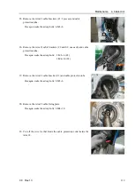
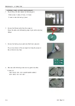
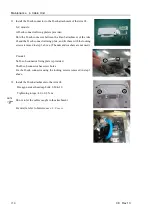
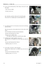
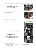
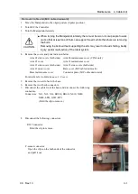
14.
Mount the brake power supply to the plate.
Mount the power so that the cables are directed down.
Cross recessed head screws with washer: 4-M3×6
Tightening torque: 0.45
±
0.1 N·m
Installation locations:
Brake power supply for Joint #5: right side
Brake power supply for Joint #6: left side
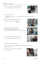
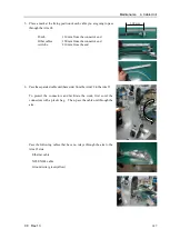
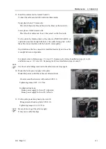
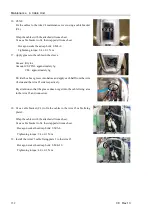
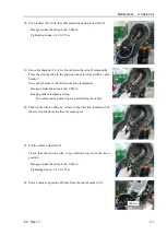
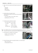
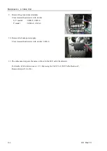
15.
Fix the cable protection plate to the Arm #4.
Hexagon socket head cap bolts: 2-M4×10
Tightening torque: 4.0
±
0.2 N·m
Be careful not to get the cables caught.
It may cause cable breakage.
NOTE
NOTE
Summary of Contents for C8 Series
Page 1: ...Rev 13 EM208R4413F 6 Axis Robots C8 series MANIPULATOR MANUAL ...
Page 2: ...Manipulator manual C8 series Rev 13 ...
Page 8: ...vi C8 Rev 13 ...
Page 14: ...Table of Contents xii C8 Rev 13 ...
Page 16: ......
Page 31: ...Setup Operation 2 Specifications C8 Rev 13 17 2 4 Outer Dimensions Unit mm 2 4 1 C8 A701 C8 ...
Page 32: ...Setup Operation 2 Specifications 18 C8 Rev 13 2 4 2 C8 A901 C8L ...
Page 33: ...Setup Operation 2 Specifications C8 Rev 13 19 2 4 3 C8 A1401 C8XL ...
Page 49: ...Setup Operation 3 Environment and Installation C8 Rev 13 35 C8 A901 C8L ...
Page 98: ......
Page 183: ...Maintenance 4 Cable Unit C8 Rev 13 169 4 2 Connector Pin Assignment 4 2 1 Signal Cable ...
Page 184: ...Maintenance 4 Cable Unit 170 C8 Rev 13 ...
Page 185: ...Maintenance 4 Cable Unit C8 Rev 13 171 ...
Page 186: ...Maintenance 4 Cable Unit 172 C8 Rev 13 4 2 2 Power Cable C8 A701 C8 C8 A901 C8L ...
Page 187: ...Maintenance 4 Cable Unit C8 Rev 13 173 C8 A1401 C8XL ...
Page 188: ...Maintenance 4 Cable Unit 174 C8 Rev 13 C8 A701 C8 C8 A901 C8L C8 A1401 C8XL ...