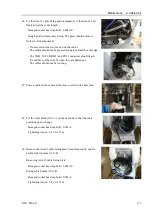
Maintenance 4. Cable Unit
C12 Rev.3
119
Installation: Cable unit (M/C cable backward)
1.
Check if the cable unit contains the following parts.
Silicone sheet: 3 sheets (25 mm
×
120 mm)
F-sensor connector housing 2 pieces
Silicon sheet
3 sheets
(25 mm
×
120 mm)
2.
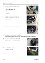
Remove the Ethernet cable from the connector.
Protect the cable ends with masking tapes to prevent the clip from
damage.
3.
Remove the locking screws and nuts of the D-sub connector.
The screws and nuts will be used again for fixing the connector.
Be careful not to lose them.
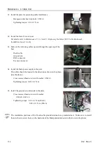
4.
Disconnect the following connectors to separate the cables.
Connectors:
X051, X061, X151, X161, XGND, BR051, BR061,
BT51, BT61, X71, X72, SW1
Summary of Contents for C12 Series
Page 1: ...Rev 3 EM204R4255F 6 Axis Robots C12 series MANIPULATOR MANUAL ...
Page 2: ...Manipulator manual C12 series Rev 3 ...
Page 8: ...vi C12 Rev 3 ...
Page 14: ...Table of Contents xii C12 Rev 3 ...
Page 16: ......
Page 30: ...Setup Operation 2 Specifications 16 C12 Rev 3 2 4 Outer Dimensions Unit mm ...
Page 84: ......
Page 155: ...Maintenance 4 Cable Unit C12 Rev 3 141 4 2 Connector Pin Assignment 4 2 1 Signal Cable ...
Page 156: ...Maintenance 4 Cable Unit 142 C12 Rev 3 ...
Page 157: ...Maintenance 4 Cable Unit C12 Rev 3 143 ...
Page 158: ...Maintenance 4 Cable Unit 144 C12 Rev 3 4 2 2 Power Cable ...


