Maintenance 4. Cable Unit
120
C12 Rev.3
5.
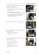
Place a mark at the fixing position of each cable you are going to pass
through the Arm #4.
D-sub
: 130 mm from the connector end
Other cables
: 190 mm from the connector end
Air tube
: 210 mm from the end
130 mm
6.
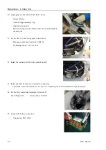
Pass the separated cable unit (base side) from the Arm #2 to the Arm #1.
To protect the connectors and facilitate the work, first cover the
connectors with a plastic bag. Then, pass the cable unit through the
arm.
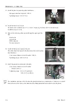
Pass the following cables that have no relays through the arm to the
Arm #3 side.
Ethernet cable
X052/X062 cable
Ground wire (green/yellow)
Summary of Contents for C12 Series
Page 1: ...Rev 3 EM204R4255F 6 Axis Robots C12 series MANIPULATOR MANUAL ...
Page 2: ...Manipulator manual C12 series Rev 3 ...
Page 8: ...vi C12 Rev 3 ...
Page 14: ...Table of Contents xii C12 Rev 3 ...
Page 16: ......
Page 30: ...Setup Operation 2 Specifications 16 C12 Rev 3 2 4 Outer Dimensions Unit mm ...
Page 84: ......
Page 155: ...Maintenance 4 Cable Unit C12 Rev 3 141 4 2 Connector Pin Assignment 4 2 1 Signal Cable ...
Page 156: ...Maintenance 4 Cable Unit 142 C12 Rev 3 ...
Page 157: ...Maintenance 4 Cable Unit C12 Rev 3 143 ...
Page 158: ...Maintenance 4 Cable Unit 144 C12 Rev 3 4 2 2 Power Cable ...


