


Maintenance 6. Joint #2
C12 Rev.3
189
Removal: Joint #2 Motor
CAUTION
■
This procedure has possibility of hands and fingers being caught and/or damage
or malfunction to the Manipulator. Be very careful when performing
maintenance.
■
Do not loosen the bolts while the Arm #2 is not tilted.
It may cause the belt come off and the Arm #2 falls down, and it is extremely
hazardous. Be sure to do the Removal steps 1 and 2 before removing the motor.
1.
Turn ON the Controller power.
2.
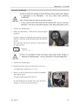
Release the Joint #2 brake. Tilt the Arm #2 and push it against
the Arm #1.
The Arm #2 falls by its weight when the Joint #2 motor unit is
removed. Therefore, release the brake and tilt the Arm #2 in
advance.
Put a cloth between the Arm #1 and Arm #2 so that the arms do
not touch each other.
EPSON
RC+
Command:
>brake off, 2
CAUTION
■
There is a possibility of hands and fingers being caught and/or damage or
malfunction to the Manipulator. Be very careful when moving the Manipulator.
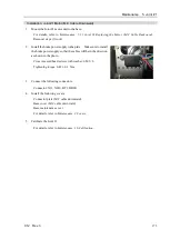
3.
Turn OFF the Controller power.
4.
Remove the Arm #1 center cover and the Arm #1 side cover.
For details, refer to
Maintenance: 3. Covers
.
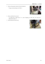
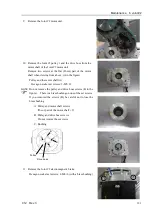
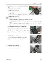
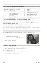
5.
Remove the heat dissipation block and the heat dissipation
sheet from the Arm #1.
Hexagon socket head cap bolts: 2-M4
×
10
The heat dissipation sheet attached to the motor unit will be
used again. Be careful not to tear and lose it.
Summary of Contents for C12 Series
Page 1: ...Rev 3 EM204R4255F 6 Axis Robots C12 series MANIPULATOR MANUAL ...
Page 2: ...Manipulator manual C12 series Rev 3 ...
Page 8: ...vi C12 Rev 3 ...
Page 14: ...Table of Contents xii C12 Rev 3 ...
Page 16: ......
Page 30: ...Setup Operation 2 Specifications 16 C12 Rev 3 2 4 Outer Dimensions Unit mm ...
Page 84: ......
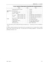
Page 155: ...Maintenance 4 Cable Unit C12 Rev 3 141 4 2 Connector Pin Assignment 4 2 1 Signal Cable ...
Page 156: ...Maintenance 4 Cable Unit 142 C12 Rev 3 ...
Page 157: ...Maintenance 4 Cable Unit C12 Rev 3 143 ...
Page 158: ...Maintenance 4 Cable Unit 144 C12 Rev 3 4 2 2 Power Cable ...