Maintenance 8. Joint #4
C12 Rev.3
223
8. Joint #4
WARNING
■
Do not connect or disconnect the motor connectors while the power to the robot
system is turned ON. Connecting or disconnecting the motor connectors with
the power ON is extremely hazardous and may result in serious bodily injury as
the Manipulator may move abnormally, and also may result in electric shock
and/or malfunction of the robot system.
■
To shut off power to the robot system, disconnect the power plug from the power
source. Be sure to connect the AC power cable to a power receptacle.
DO NOT connect it directly to a factory power source.
■
Before performing any replacement procedure, turn OFF the Controller and
related equipment, and then disconnect the power plug from the power source.
Performing any replacement procedure with the power ON is extremely hazardous
and may result in electric shock and/or malfunction of the robot system.
CAUTION
■
Be careful not to apply excessive shock to the motor shaft during replacement.
The shock may shorten the life of the motors and encoder and/or damage them.
■
Never disassemble the motor and the encoder. Disassembled motor and
encoder will cause a positional gap and cannot be used again.
After parts have been replaced (motors, reduction gear units, timing belts, etc.), the
Manipulator cannot perform positioning properly because a gap exists between the origin
stored in each motor encoder and its corresponding origin stored in the Controller.
Therefore, it is necessary to match these origins after replacing the parts.
The process of aligning the two origins is called “Calibration”.
Refer to
Maintenance 16. Calibration
and perform the calibration after the parts replacement.
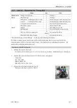
Joint #4 Electromagnetic brake
Joint #4 Motor
Joint #4 Reduction gear unit
Joint #4 Timing belt
Summary of Contents for C12 Series
Page 1: ...Rev 3 EM204R4255F 6 Axis Robots C12 series MANIPULATOR MANUAL ...
Page 2: ...Manipulator manual C12 series Rev 3 ...
Page 8: ...vi C12 Rev 3 ...
Page 14: ...Table of Contents xii C12 Rev 3 ...
Page 16: ......
Page 30: ...Setup Operation 2 Specifications 16 C12 Rev 3 2 4 Outer Dimensions Unit mm ...
Page 84: ......
Page 155: ...Maintenance 4 Cable Unit C12 Rev 3 141 4 2 Connector Pin Assignment 4 2 1 Signal Cable ...
Page 156: ...Maintenance 4 Cable Unit 142 C12 Rev 3 ...
Page 157: ...Maintenance 4 Cable Unit C12 Rev 3 143 ...
Page 158: ...Maintenance 4 Cable Unit 144 C12 Rev 3 4 2 2 Power Cable ...


