


Setup & Operation 4. End Effectors
C12 Rev.3
43
Calculate the Weight parameter by using the formula below and enter the value.
Weight Parameter Formula
Weight parameter = M
w
+ W
a
+ W
b
M
w
W
a
W
b
: Load on the fore end of Arm #6 (kg)
: Equivalent weight of the Arm #3 deck (kg)
: Equivalent weight of the Arm #5 deck (kg)
W
a
= M
a
(L
a
)²/ (L)²
W
b
= M
b
(L
b
)²/ (L)²
M
a
M
b
L
L
a
L
b
: Weight of the air valve on the Arm #3 deck
: Weight of the camera on the Arm #5 deck
: Length of the upper arm (315 mm)
: Distance between the Joint #3 and the center of gravity of
the air valve on the Arm #3 deck (mm)
: Distance between the Joint #3 and the center of gravity
of the camera on the Arm #5 deck (mm)
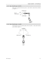
<Example> The fore end of the Arm #6 is 730 mm (L) away from the Joint #3
of C12-A1401** (C12XL).
Load on the fore-end of Arm #6 is 5 kg (M
w
).
Load on the Arm #3 deck is 1.5 kg (M
a
).
The deck is 0 mm (L
a
) away from Joint #3.
Load on the Arm #5 deck is 1.0 kg (M
b
).
The deck is 690 mm (L
b
) away from the Joint #3.
W
a
=1.5 × 0
2
/730
2
=0
W
b
=1.0 × 690
2
/730
2
=0.89
→
0.9 (round up)
M
w
+ W
a
+ W
b
=5 + 0 + 0.9=5.9
Enter “5.9” for the Weight parameter.
Summary of Contents for C12 Series
Page 1: ...Rev 3 EM204R4255F 6 Axis Robots C12 series MANIPULATOR MANUAL ...
Page 2: ...Manipulator manual C12 series Rev 3 ...
Page 8: ...vi C12 Rev 3 ...
Page 14: ...Table of Contents xii C12 Rev 3 ...
Page 16: ......
Page 30: ...Setup Operation 2 Specifications 16 C12 Rev 3 2 4 Outer Dimensions Unit mm ...
Page 84: ......
Page 155: ...Maintenance 4 Cable Unit C12 Rev 3 141 4 2 Connector Pin Assignment 4 2 1 Signal Cable ...
Page 156: ...Maintenance 4 Cable Unit 142 C12 Rev 3 ...
Page 157: ...Maintenance 4 Cable Unit C12 Rev 3 143 ...
Page 158: ...Maintenance 4 Cable Unit 144 C12 Rev 3 4 2 2 Power Cable ...