


Maintenance 2. General Maintenance
86
C12 Rev.3
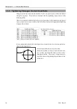
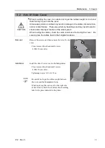
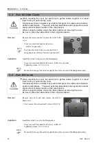
2.4 Tightening Hexagon Socket Head Bolts
Hexagon socket head cap bolts (hereinafter, “bolts”) are used in places where mechanical
strength is required. These bolts are fastened with the tightening torque shown in the
following tables.
When it is required to refasten the bolts in some procedures in this manual (except special
cases as noted), use a torque wrench so that the bolts are fastened with appropriate tightening
torque as shown below.
Bolt
Tightening Torque
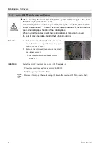
See below for the set screw.
M3
2.0 ± 0.1 N
⋅
m (21 ± 1 kgf
⋅
cm)
Set Screw
Tightening Torque
M4
4.0 ± 0.2 N
⋅
m (41 ± 2 kgf
⋅
cm)
M4
2.4 ± 0.1 N
⋅
m (26 ± 1 kgf
⋅
cm)
M5
8.0 ± 0.4 N
⋅
m (82 ± 4 kgf
⋅
cm)
M5
3.9 ± 0.2 N
⋅
m (40 ± 2 kgf
⋅
cm)
M6
13.0 ± 0.6 N
⋅
m (133 ± 6 kgf
⋅
cm)
M6
8.0 ± 0.4 N
⋅
m (82 ± 4 kgf
⋅
cm)
M8
32.0 ± 1.6 N
⋅
m (326 ± 16 kgf
⋅
cm)
M10 58.0 ± 2.9 N
⋅
m (590 ± 30 kgf
⋅
cm)
M12 100.0 ± 5.0 N
⋅
m (1,020 ± 51 kgf
⋅
cm)
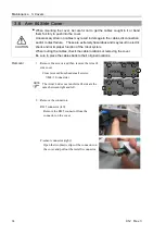
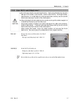
It is recommended to fasten the bolts aligned on a circumference in a crisscross pattern as
shown in the figure below.
1
5
3
7
2
6
4
8
Bolt hole
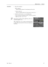
Do not fasten all bolts securely at one time.
Divide the number of times to fasten the bolts into
two or three and fasten the bolts securely with a
hexagonal wrench. Then, use a torque wrench to
fasten the bolts with tightening torques shown in the
table above.
Summary of Contents for C12 Series
Page 1: ...Rev 3 EM204R4255F 6 Axis Robots C12 series MANIPULATOR MANUAL ...
Page 2: ...Manipulator manual C12 series Rev 3 ...
Page 8: ...vi C12 Rev 3 ...
Page 14: ...Table of Contents xii C12 Rev 3 ...
Page 16: ......
Page 30: ...Setup Operation 2 Specifications 16 C12 Rev 3 2 4 Outer Dimensions Unit mm ...
Page 84: ......
Page 155: ...Maintenance 4 Cable Unit C12 Rev 3 141 4 2 Connector Pin Assignment 4 2 1 Signal Cable ...
Page 156: ...Maintenance 4 Cable Unit 142 C12 Rev 3 ...
Page 157: ...Maintenance 4 Cable Unit C12 Rev 3 143 ...
Page 158: ...Maintenance 4 Cable Unit 144 C12 Rev 3 4 2 2 Power Cable ...