


Maintenance 3. Covers
94
C12 Rev.3
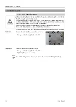
3.6 Arm #4 Side Cover
CAUTION
■
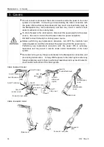
When mounting the cover, be careful not to get the cables caught in it or bend
them forcibly to push into the cover.
Unnecessary strain on cables may result in damage to the cables, disconnection,
and/or contact failure. These are extremely hazardous and may result in electric
shock and/or improper function of the robot system.
When routing the cables, check the cable locations at removing the cover.
Be sure to place the cables back to their original locations.
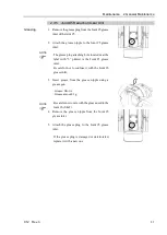
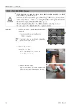
Removal
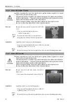
1.
Remove the screws and then remove the Arm #4
side cover.
Cross recessed truss head small screws:
7-M4×10 (one side)
The Arm #4 side cover and Arm #4 side are the
same between right and left.
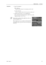
2.
Remove the connectors.
RJ45 connector (left):
Remove the RJ45 connector from the
connector on the cover.
F-sensor connector (right):
Open the two plastic clips of the connector on
the cover and pull out the metallic connector.
NOTE
Summary of Contents for C12 Series
Page 1: ...Rev 3 EM204R4255F 6 Axis Robots C12 series MANIPULATOR MANUAL ...
Page 2: ...Manipulator manual C12 series Rev 3 ...
Page 8: ...vi C12 Rev 3 ...
Page 14: ...Table of Contents xii C12 Rev 3 ...
Page 16: ......
Page 30: ...Setup Operation 2 Specifications 16 C12 Rev 3 2 4 Outer Dimensions Unit mm ...
Page 84: ......
Page 155: ...Maintenance 4 Cable Unit C12 Rev 3 141 4 2 Connector Pin Assignment 4 2 1 Signal Cable ...
Page 156: ...Maintenance 4 Cable Unit 142 C12 Rev 3 ...
Page 157: ...Maintenance 4 Cable Unit C12 Rev 3 143 ...
Page 158: ...Maintenance 4 Cable Unit 144 C12 Rev 3 4 2 2 Power Cable ...