


Maintenance 4. Cable Unit
110
C12 Rev.3
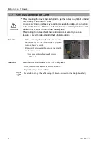
8.
Remove the ground wire plate (M/C cable backward).
Hexagon socket head cap bolts: 2-M4
×
10
9.
Remove the ground wire terminals.
Cross recessed head screws with washer
: 9-M4
×
8, 2-M3
×
6
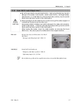
10.
Remove the brake power supply.
Cross recessed head screws with washer: 2-M3
×
6
11.
Disconnect the following cables through the opening of the base.
D-sub cable
Ground wire
RJ45 connector
F-sensor connector
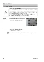
12.
Remove the Joint #1 motor unit.
For details, refer to
Maintenance: 5.1.1 Joint #1 - Replacing the Motor (M/C Cable Backward,
Removal steps (6) and (7).
13.
Remove the plate for preventing cable interference.
Hexagon socket head cap bolts: 2-M3
×
6
Summary of Contents for C12 Series
Page 1: ...Rev 3 EM204R4255F 6 Axis Robots C12 series MANIPULATOR MANUAL ...
Page 2: ...Manipulator manual C12 series Rev 3 ...
Page 8: ...vi C12 Rev 3 ...
Page 14: ...Table of Contents xii C12 Rev 3 ...
Page 16: ......
Page 30: ...Setup Operation 2 Specifications 16 C12 Rev 3 2 4 Outer Dimensions Unit mm ...
Page 84: ......
Page 155: ...Maintenance 4 Cable Unit C12 Rev 3 141 4 2 Connector Pin Assignment 4 2 1 Signal Cable ...
Page 156: ...Maintenance 4 Cable Unit 142 C12 Rev 3 ...
Page 157: ...Maintenance 4 Cable Unit C12 Rev 3 143 ...
Page 158: ...Maintenance 4 Cable Unit 144 C12 Rev 3 4 2 2 Power Cable ...