


Maintenance 5. Joint #1
174
C12 Rev.3
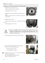
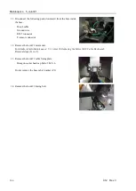
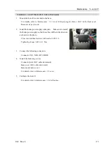
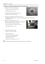
6.
Remove the Joint #1 brake plate from the Joint #1 motor unit.
Hexagon socket head cap bolts: 3-M4
×
20
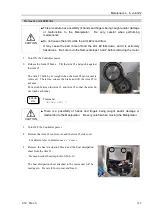
7.
Remove the Joint #1 motor unit from the base.
Hexagon socket head cap bolts: 3-M6
×
30 (with a plain washer)
Be careful not to tear and lose the heat radiation sheet attached to the motor.
Summary of Contents for C12 Series
Page 1: ...Rev 3 EM204R4255F 6 Axis Robots C12 series MANIPULATOR MANUAL ...
Page 2: ...Manipulator manual C12 series Rev 3 ...
Page 8: ...vi C12 Rev 3 ...
Page 14: ...Table of Contents xii C12 Rev 3 ...
Page 16: ......
Page 30: ...Setup Operation 2 Specifications 16 C12 Rev 3 2 4 Outer Dimensions Unit mm ...
Page 84: ......
Page 155: ...Maintenance 4 Cable Unit C12 Rev 3 141 4 2 Connector Pin Assignment 4 2 1 Signal Cable ...
Page 156: ...Maintenance 4 Cable Unit 142 C12 Rev 3 ...
Page 157: ...Maintenance 4 Cable Unit C12 Rev 3 143 ...
Page 158: ...Maintenance 4 Cable Unit 144 C12 Rev 3 4 2 2 Power Cable ...