


Setup & Operation 5. Motion Range
54
C12 Rev.3
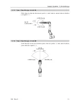
5.2 Motion Range Setting by Mechanical Stops
Using the adjustable mechanical stops physically limits the absolute area that the
Manipulator can move.
Be sure to turn OFF the Manipulator in advance.
Use bolts conforming to the specified length and surface processing (ex:
nickel plating
) with
high corrosion resistance.
Specify the pulse range again after changing the position of the mechanical stop.
For details on the pulse range setting, refer to the
Setup & Operation 5.1 Motion Range
Setting by Pulse Range (for All Arms)
.
Be sure to set the pulse range not to exceed the setting angles of the mechanical stop.
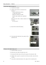
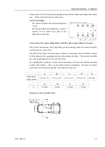
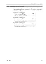
5.2.1 Motion Range Setting of Joint #1
Install the adjustable mechanical stop (J1) to the threaded hole corresponding to the angle
you want to set.
Normally the mechanical stop is not installed.
Hexagon socket head cap bolt M12×30×2 bolts
Tightening torque
42.0 ± 2.1N·m (428 ± 21 kgf·cm)
a
b
c
a
b
c
Angle (
°
)
−
145, +110
−
110, +145
±
240
Pulse (pulse)
−
9507650
+7212700
−
7212700
+9507650
±
15736800
Adjustable mechanical stop (J1)
Applied
Applied
Not applied
(standard)
Summary of Contents for C12 Series
Page 1: ...Rev 3 EM204R4255F 6 Axis Robots C12 series MANIPULATOR MANUAL ...
Page 2: ...Manipulator manual C12 series Rev 3 ...
Page 8: ...vi C12 Rev 3 ...
Page 14: ...Table of Contents xii C12 Rev 3 ...
Page 16: ......
Page 30: ...Setup Operation 2 Specifications 16 C12 Rev 3 2 4 Outer Dimensions Unit mm ...
Page 84: ......
Page 155: ...Maintenance 4 Cable Unit C12 Rev 3 141 4 2 Connector Pin Assignment 4 2 1 Signal Cable ...
Page 156: ...Maintenance 4 Cable Unit 142 C12 Rev 3 ...
Page 157: ...Maintenance 4 Cable Unit C12 Rev 3 143 ...
Page 158: ...Maintenance 4 Cable Unit 144 C12 Rev 3 4 2 2 Power Cable ...