


Maintenance 3. Covers
100
C12 Rev.3
Installation
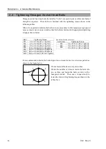
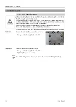
1.
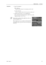
Install the spacers to the holes on the gasket.
(11 places)
2.
Apply the liquid gasket to the base rear gasket.
Install the base rear gasket to the base cover.
(See the figure for gasket applying points)
Base rear gasket
Gasket
Applying
point (×11)
Spacer (×11)
Base cover
After applying the liquid gasket, leave the gasket until the liquid gasket becomes
solid and the gasket is fixed.
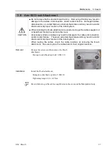
3.
Install the base cover to the Manipulator.
Hexagon socket head cap bolts: 11-M4×10
Tightening torque: 4.0
±
0.2 N·m
Be careful not to get the gasket and cables caught between
the cover and the Manipulator body.
Replace the gasket if there are flaws or deteriorations.
For cleanroom model, install the gasket between the heat
sink and the base cover.
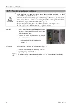
4.
Install the heat sink.
Hexagon socket head cap bolts: 4-M4×15
Tightening torque: 4.0
±
0.2 N·m
5.
Install the fan.
For details, refer to
Maintenance 15.
Replacing the Fan.
NOTE
NOTE
NOTE
Summary of Contents for C12 Series
Page 1: ...Rev 3 EM204R4255F 6 Axis Robots C12 series MANIPULATOR MANUAL ...
Page 2: ...Manipulator manual C12 series Rev 3 ...
Page 8: ...vi C12 Rev 3 ...
Page 14: ...Table of Contents xii C12 Rev 3 ...
Page 16: ......
Page 30: ...Setup Operation 2 Specifications 16 C12 Rev 3 2 4 Outer Dimensions Unit mm ...
Page 84: ......
Page 155: ...Maintenance 4 Cable Unit C12 Rev 3 141 4 2 Connector Pin Assignment 4 2 1 Signal Cable ...
Page 156: ...Maintenance 4 Cable Unit 142 C12 Rev 3 ...
Page 157: ...Maintenance 4 Cable Unit C12 Rev 3 143 ...
Page 158: ...Maintenance 4 Cable Unit 144 C12 Rev 3 4 2 2 Power Cable ...