Expansion Bus
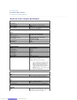
Bus type
PCI 2.2
SATA 1.0a and 2.0
USB 2.0
Bus speed
PCI: 33 MHz
SATA: 1.5 and 3.0 Gbps
USB: 480 Mbps
Cards:
low-profile cards supported
PCI:
connector
one
connector size
120 pins
connector data width (maximum)
32 bits
Drives
Externally accessible
one bay for a slimline floppy drive;
one bay for a slimline CD/DVD drive
Internally accessible
one bay for a 1-inch-high hard drive
Connectors
External connectors:
Serial
9-pin connector; 16550C-compatible
Parallel
25-hole connector (bidirectional)
Video
15-hole VGA connector
Network adapter
RJ45 connector
USB
two front-panel and six back-panel USB 2.0
–
compliant connectors
Audio
three connectors for line-in, line-out, and microphone;
one front-panel connector for headphones
System board connectors:
Primary IDE drive
40-pin connector
Serial ATA
7-pin connector
Floppy drive
34-pin connector
Serial
12-pin connector for optional second serial port card
Fan
5-pin connector
PCI 2.2
120-pin connector
CD drive audio interface
4-pin connector
Front panel
40-pin connector
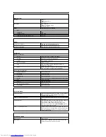
Key Combinations
<Ctrl><Alt><Del>
in Microsoft
®
Windows
®
XP, brings up the Windows
Security window; in MS-DOS
®
mode, restarts
(reboots) the computer
<F2> or <Ctrl><Alt><Enter>
starts embedded system setup (during system start-
up only)
<Ctrl><Alt><b>
automatically starts the computer from the network
environment specified by the remote boot
environment (PXE) rather than from one of the
devices in the system setup
Boot Sequence
option
(during system start-up only)
<F12> or <Ctrl><Alt><F8>
displays a boot device menu that allows the user to
enter a device for a single boot (during system start-
up only) as well as options to run hard-drive and
system diagnostics
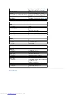
Controls and Lights
Power control
push button
Power light
green light
—
Blinking green indicates sleep mode;
solid green indicates power-on state.
Summary of Contents for OptiPlex GX520
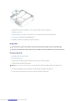
Page 22: ...4 Press Alt b to restart the computer and implement your changes Back to Contents Page ...
Page 29: ......
Page 97: ...Back to Contents Page ...
Page 108: ......
Page 145: ......
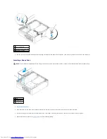
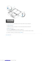
Page 149: ...10 Replace the computer cover Back to Contents Page 3 captive screw housing 2 ...
Page 157: ...Back to Contents Page ...
Page 166: ...Back to Contents Page ...
Page 181: ...10 Replace the computer cover Back to Contents Page 3 captive screw in housing 2 ...
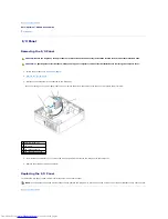
Page 222: ...Back to Contents Page Dell OptiPlex GX520 User s Guide Back to Contents Page ...

