

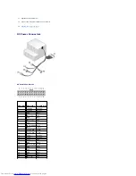


DC Power Connector P2
DC Power Connector P3
DC Power Connector P4
DC Power Connector P5 and P6
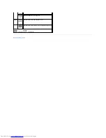
22
VCC (+5V)
Red
23
VCC (+5V)
Red
24
GND
Black
*Use 22-AWG wire instead of 18-AWG wire.
Pin Number
Signal Name
18-AWG Wire
1
COM
Black
2
COM
Black
3
+12 VDC
Yellow
4
+12 VDC
Yellow
Pin Number
Signal name
18-AWG Wire
1
+12 VDC
Yellow
2
COM
Black
3
COM
Black
4
+5 VDC
Red
Pin Number
Signal Name
22-AWG Wire
1
+5 VCD
Red
2
COM
Black
3
COM
Black
4
+12 VDC
Yellow
Summary of Contents for OptiPlex GX520
Page 22: ...4 Press Alt b to restart the computer and implement your changes Back to Contents Page ...
Page 29: ......
Page 97: ...Back to Contents Page ...
Page 108: ......
Page 145: ......
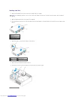
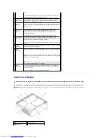
Page 149: ...10 Replace the computer cover Back to Contents Page 3 captive screw housing 2 ...
Page 157: ...Back to Contents Page ...
Page 166: ...Back to Contents Page ...
Page 181: ...10 Replace the computer cover Back to Contents Page 3 captive screw in housing 2 ...
Page 222: ...Back to Contents Page Dell OptiPlex GX520 User s Guide Back to Contents Page ...