devices per channel with one channel
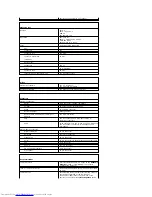
Expansion Bus
Bus type
PCI 2.3
SATA 1.0a and 2.0
USB 2.0
PCI Express 1.0a
Bus speed
PCI: 33 MHz
SATA: 1.5 Gbps and 3.0 Gbps
USB: 480 Mbps
PCI Express x1: 5 Gbps
Cards:
full-height cards supported
PCI:
connectors
two
connector size
120 pins
connector data width
(maximum)
32 bits
PCI Express:
connectors
one x1
power
10 W maximum
connector size
36 pins
connector data width (maximum)
one PCI Express lane
Drives
Externally accessible
one 3.5-inch drive
two 5.25-inch drive bays
Internally accessible
two bays for 1-inch-high hard drives
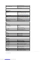
Connectors
External connectors:
Serial
9-pin connector; 16550C-compatible
Parallel
25-hole connector (bidirectional)
Video
15-hole VGA connector
Network adapter
RJ45 connector
Optional PS/2 with secondary serial port
adapter
two 6-pin mini-DINs
USB
two front-panel and six back-panel USB 2.0
–
compliant connectors
Audio
three connectors for line-in, line-out, and microphone;
two front-panel connectors for headphones and
microphone
System board connectors:
Primary IDE drive
40-pin connector
Serial ATA
four 7-pin connectors
Floppy drive
34-pin connector
Serial
12-pin connector for optional second serial port card
Fan
5-pin connector
PCI 2.2
120-pin connector
CD drive audio interface
4-pin connector
Front panel
40-pin connector
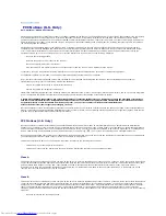
Key Combinations
<Ctrl><Alt><Del>
in Microsoft
®
Windows
®
XP, brings up the
Windows
Security
window.; in MS-DOS
®
mode, restarts
(reboots) the computer
<F2> or <Ctrl><Alt><Enter>
starts embedded system setup (during system start-
up only)
<Ctrl><Alt><b>
automatically starts the computer from the network
environment specified by the remote boot
environment (PXE) rather than from one of the
devices in the system setup
Boot Sequence
option
Summary of Contents for OptiPlex GX520
Page 22: ...4 Press Alt b to restart the computer and implement your changes Back to Contents Page ...
Page 29: ......
Page 97: ...Back to Contents Page ...
Page 108: ......
Page 145: ......
Page 149: ...10 Replace the computer cover Back to Contents Page 3 captive screw housing 2 ...
Page 157: ...Back to Contents Page ...
Page 166: ...Back to Contents Page ...
Page 181: ...10 Replace the computer cover Back to Contents Page 3 captive screw in housing 2 ...
Page 222: ...Back to Contents Page Dell OptiPlex GX520 User s Guide Back to Contents Page ...


