BE1-951
Protection and Control
4-43
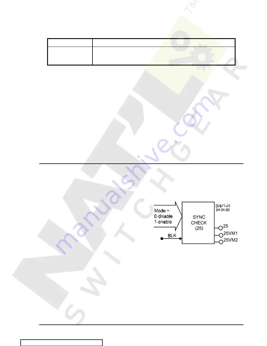
Figure 4-25. Sync-Check Element
recognizes that a non-blocked low set (50TP or 50 TN) element picked up and reset before timing out to trip.
Table 4-33 summarizes the zone sequence coordination settings.
Table 4-33. Zone Sequence Coordination Settings
Function
Range/Purpose
Zone Pickup Logic
The zone sequence pickup logic defines which logic elements should be
considered zone sequence pickups. Only OR (+) logic can be used—no
AND (
9
) variables may be used.
SP-79ZONE Command
Purpose:
Read or set the 79 Zone Sequence Logic.
Syntax:
SP-79ZONE[=<Zone Pickup Logic>]
Comments: A logic zero disables zone sequence coordination. See Table 4-31 for SP-79ZONE settings
information.
SP-79ZONE Command Example
1.
Increment the 79 automatic reclose count if one or more 50 phase or neutral elements picks up and
all are cleared without a Trip operation.
>SP-79ZONE=50TNPU
Recloser zone sequence coordination detects when a fault has been cleared by a downstream recloser and
increments the upstream 79 automatic reclose count to maintain a consistent count with the other recloser.
A fault is presumed cleared downstream when one or more protective functions pickup and dropout with no
trip occurring. If the zone pickup logic becomes TRUE and then FALSE without a trip output operating, then
the 79 automatic reclose counter should be incremented. The shot counter is reset by the max cycle timer.
So its 79ZONE is used, this function cannot be disabled.
SYNCHRONISM CHECK PROTECTION
25 Synchronism Check
Figure 4-25 illustrates the inputs and outputs of the Sync-Check element. Element operation is described
in the following paragraphs.
The Sync-Check element has one output: 25. When
monitored voltage between the systems as measured by
the phase VTs and the auxiliary Vx input circuits meets
angle, voltage, and slip criteria, the 25 output becomes
TRUE.
The Block (BLK) input is used to disable Sync-Checking.
A BESTlogic expression defines how the BLK input
functions. When this expression is true, the element is
disabled by forcing the outputs to logic 0. This feature
functions in a similar way to the torque control contact of
an electromechanical relay.
The 25 element is enabled or disabled by the mode input. Two modes are available, Selecting Mode 0
disables the 25 element. Mode 1 enables the 25 element.
The 25 function module will change the 25 output to TRUE if the following conditions are met:
a) Phase angle between systems is less than setting.
b) Frequency error between systems is less than setting. As an additional parameter, the relay can
be set to only allow generator frequency greater than bus frequency.
c)
Voltage magnitude between systems is less than setting (the voltage used by the relay for this
feature is a voltage magnitude measurement, not a voltage phasor measurement).


