6-16
Reporting and Alarm Functions
BE1-951
Setting the Breaker Duty Monitoring Function
Breaker duty monitoring is programmed using the SB-DUTY (setting breaker, duty) command. Settings for
breaker duty monitoring are summarized in Table 6-8.
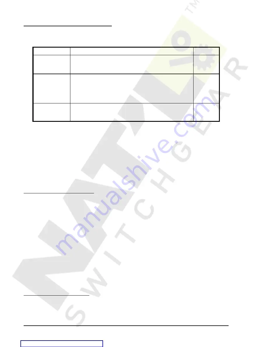
Table 6-8. Breaker Duty Monitoring Settings
Function
Range/Purpose
Default
mode
0 = disabled
1 =
I
2 =
I
2
0
dmax
0 to 4.2e+7
The dmax parameter represents the maximum duty that the
breaker contacts can withstand before needing service.
dmax is programmed in primary amperes using exponential
floating point format.
0e+0
BLKBKR logic
OR logic term (e.g., IN1, or VO7) that blocks the breaker
monitoring logic when TRUE (1). A setting of 0 disables
blocking (breaker operations are no longer counted).
0
SB-DUTY Command
Purpose:
Read or set the breaker contact duty.
Syntax: SB-DUTY[=<mode>,<dmax>,<BLKBKR logic>]
Comments:
Password access privilege G or S is required to change settings. See Table 6-8 for SB-
DUTY settings information.
SB-DUTY Command Example
1.
Enable breaker monitoring with duty calculated as
*
I
2
. Maximum duty should be 20 kilo-amperes.
Breaker monitoring should be blocked when input 3 is energized.
>SB-DUTY=2,20E3,IN3
Retrieving Breaker Duty Information
Breaker duty values can be read at HMI screen 4.3.2. Duty values can be changed by using the front panel
Edit key. Write access to reports is required to edit breaker duty values. Duty values can also be read or
changed through the communication ports using the RB-DUTY command.
RB-DUTY Command
Purpose:
Read or set the breaker contact duty log.
Syntax: RB-DUTY<phase>[=<%duty>]
Comments:
phase = A, B, or C. No entry for <phase> will read or write to all phases.
%duty = accumulated duty expressed in percent of DMAX (set by SB-DUTY command)
RB-DUTY Command Examples
1.
Read all contact duty values.
RB-DUTY
RB-DUTYA=92%; RB-DUTYB=23%; RB-DUTYC=28%
2.
Reset the A-phase duty after maintenance was performed.
RB-DUTYA=0
Breaker Operate Time Monitoring
The breaker operate time monitor tracks the time from when a trip output occurs (defined by the TRIP logic
expression) to when the fast dropout current detector observes that current is zero in all three breaker poles.
This time is reported as a line in the fault summary reports. See the Fault Reporting subsection for more
information about the TRIP logic expression and Fault Summary Reports.


