background image

Operation using HART communicator

Azbil Corporation

7-4

Model MTG11A/18A, MTG11B/18B, MTG14C

7-1-3 : Verifying communication

After the HART Communicator has been properly interconnected, turn the device's 
power on. For the external power supply model, turn on the external power supply 
before turning the device power on.

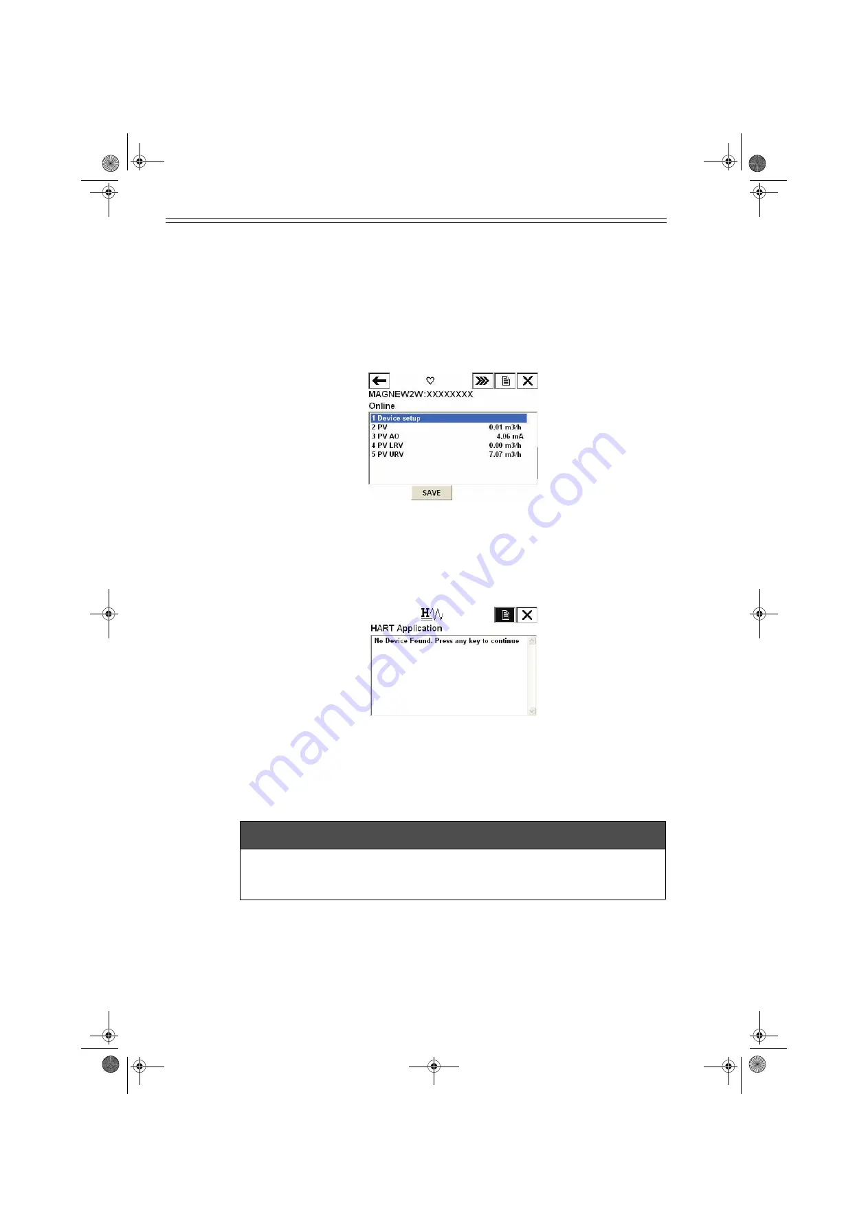
Once the setting and wiring connections are correct, the HART Communicator's 
display shows an online menu as shown below and a HART mark will flicker in the 
upper right hand corner of the display.

Figure 7-2  Online menu

If the display is not as shown in Figure 7-2 but as shown in Figure 7-3 below, no 
communications are being made. Recheck the HART Communicator connections and 
the setting of converter. (The setting of the converter is described page 7-2.)

Figure 7-3  Communication not available

7-1-4 : Cautions

m

 CAUTION

Do not remove the HART Communicator cable from the converter while executing 
communication. If the cable is disconnected during data setting transmission there 
will be no data transfer to the converter.

CM2-MTG300-2001.book  4 ページ  2015年9月29日 火曜日 午前10時14分

Summary of Contents for MagneW Neo PLUS

Page 1: ...MagneW Neo PLUS MagneW Two wire PLUS Smart Two wire Electromagnetic Flowmeter Model MTG11A 18A MTG11B 18B MTG14C Converter User s Manual CM2 MTG300 2001...

Page 2: ...ss for a particular purpose and makes no express warranty except as may be stated in its written agreement with and for its customer In no event shall Azbil Corporation be liable to anyone for any ind...

Page 3: ...ic flowmeter The MagneW Neo MagneW Two wire PLUS is a landmark electromagnetic flowmeter that is operated on 4 20 mA DC Based on our extensive experience in the field meticulous care is taken in the d...

Page 4: ...ce are written on the nameplate of the main unit Compare these specifications with those listed in the specification sheets device standard specifications and model number and verify that all the spec...

Page 5: ...Tighten the display cover and terminal box cover in order to prevent moisture ingression 3 Return the instrument to its original packing 4 Store the device indoors at room temperature and humidity in...

Page 6: ...shut down of this instrument Chapter 5 To manipulate the instrument either its data setting device or a communication line may be used This chapter describes the operation by using the data setting d...

Page 7: ...cazione ATEX tipo n Italiano 1 26 1 ATEX Type n Certificering Dutch 1 28 1 Certifica o de tipo n ATEX Portugu s 1 30 1 NEPSI Ex nA Certification English 1 32 1 3 2 MTG18B and MTG14C 1 35 FM approval w...

Page 8: ...ctions of the data setting device 5 5 5 2 1 Data setting device 5 5 5 3 Description of MEASURING MODE 5 7 5 3 1 Display overview 5 7 5 3 2 Display of write protect level 5 8 5 4 Overview of operation...

Page 9: ...ion of CALIBRATION MODE 5 68 5 7 7 Manual zero 5 72 5 7 8 Configuration of CRITICAL MODE 5 74 5 7 9 Displaying ROM version and date 5 75 5 7 10 Returning to settings at shipment 5 76 5 8 Description o...

Page 10: ...gh low alarm values ALARM CONFIG function 6 54 Deciding fail safe direction F S SET UP function 6 56 Setting burnout direction of pulse output F S SETUP function 6 58 Select pulse output contact outpu...

Page 11: ...etting the totalized value 7 22 7 2 6 Contact output setting 7 23 High alarm value setting 7 23 Low alarm value setting 7 24 Contact output status setting 7 24 7 2 7 Burnout setting 7 25 Analog output...

Page 12: ...dicator data setting device 8 2 8 1 2 Replacement of the electronic unit for the ATEX Ex dmbia or NEPSI Ex dmia model 8 3 8 2 Troubleshooting 8 6 Types of troubles 8 6 Troubles at startup 8 7 Troubles...

Page 13: ...Straight pipe section upstream of detector D Nominal detector bore diameter 2 4 Figure 2 3 Maintenance space 2 5 Figure 2 4 Change the direction of converter 2 6 Figure 2 5 Changing the display data...

Page 14: ...nternal grounding terminal 3 6 Figure 3 3 Grounding procedure that uses external grounding terminal 3 6 Figure 3 4 Wire connection diagram 3 7 Figure 3 5 Wire connection diagram When inputting to the...

Page 15: ...of gaskets 2 28 Table 6 1 Spare parts for integral type 6 7 Table 6 2 Spare parts for remote type converter Model MTG11B 6 9 Table 6 3 Spare parts for remote type detector Mode MTG11B 6 10 Table 6 4 W...

Page 16: ...List of Figures Tables CM2 MTG300 2001 book 4...

Page 17: ...14C System configuration and structure Outline of this chapter This chapter presents the equipment configuration of a measuring system using this instrument It also describes the structure and the nam...

Page 18: ...t an analog output Digital output DE output Use this system configuration if the instantaneous flow rate values instrument database and self diagnosis results are to be output as digital variables DE...

Page 19: ...communicate with this instrument read data and change the instrument data settings Figure 1 2 1 System configuration for analog output 1 Integral type Figure 1 2 2 System configuration for analog out...

Page 20: ...t be set For DD device description of the HART Communicator use the HCF DD Library Host DD Distribution HCF KIT III Release 2010 Number 1 Device Description 1 Device Revision 2 or later This instrumen...

Page 21: ...is pulse output method to use the transistor contact Figure 1 3 1 System configuration for analog output 2 Integral type Figure 1 3 2 System configuration for analog output Remote type Communicator SF...

Page 22: ...utput and displays the totalized value Note Open collector pulse output method using the transistor contact Figure 1 4 1 System configuration for analog output 1 Integral type Figure 1 4 2 System conf...

Page 23: ...the contact output together and the wiring of the flowmeter pulse output and the contact output are same as mentioned is the System configuration on page 1 5 and page 1 6 In this system configuration...

Page 24: ...Communicator SFC Used to communicate with this instrument read data and change instrument data settings PM100 PM300 A MC These are process controllers on the UCN which carries out the regulatory contr...

Page 25: ...ts of a detector and converter The converter consists of the converter proper indicator data setting device and terminal box Figure 1 6 1 shows overview of the instrument For detailed specification an...

Page 26: ...ts the signal of electromotive force generated by the detector into an instantaneous flow rate value and outputs it as a flow rate signal Special cable It transmits the electromotive force and the exc...

Page 27: ...various parts The following table describes the various parts of the detector Figure 1 7 Detector details Flanged detector Name Description Flow direction mark Indicates the flow direction of the flu...

Page 28: ...functions of various parts The following table describes the various parts of the detector Figure 1 8 Detector details wafer type detector Name Description Flow direction mark Indicates the flow direc...

Page 29: ...ator face can be turned at intervals of 90 degrees through one turn Refer to Changing the direction of display data setting device on page 2 8 Names of various parts The names of various parts of the...

Page 30: ...inal box details Figure 1 12 1 Terminal block integral type Figure 1 12 2 Terminal block remote type Terminal box cover External grounding terminal Conduit for an output signal line Internal grounding...

Page 31: ...for flow measurement Improper grounding can cause malfunctions The most effective grounding method is direct connection to earth ground with minimal impedance Internal ground ing terminal If suscepti...

Page 32: ...alled in accordance with the relevant requirements of the National Electrical Code ANSI NFPA70 Grounding To maintain Intrinsic safety of system connect conductor to earth ground so that it has less th...

Page 33: ...2 Groups A B C and D Class II Division 2 Groups E F G Class III Input rating 42V dc 4 20mA Provides Non Incendive circuit to sensing electrodes Enclosure Type 4X IP67 MWP 3 0 MPa max Temperature Code...

Page 34: ...standards EN 60079 0 2006 Electrical apparatus for explosive gas atmospheres Part 0 General requirements EN 60079 15 2005 Electrical apparatus for explosive gas atmospheres Part 15 Construction test...

Page 35: ...Azbil Corporation Model MTG11A 18A 11B 18B 14C System configuration and structure Model MTG11A 18A MTG11B 18B MTG14C 1 19 CM2 MTG300 2001 book 19...

Page 36: ...0 2006 Mat riel lectrique pour atmosph res explosives gazeuses Partie 0 R gles g n rales EN 60079 15 2005 Mat riel lectrique pour atmosph res explosives gazeuses Partie 15 Construction essais et marqu...

Page 37: ...Azbil Corporation Model MTG11A 18A 11B 18B 14C System configuration and structure Model MTG11A 18A MTG11B 18B MTG14C 1 21 CM2 MTG300 2001 book 21...

Page 38: ...mittel f r gasexplosionsgef hrdete Bereiche Teil 0 Allgemeine Anforderungen EN 60079 15 2005 Elektrische Betriebsmittel f r gasexplosionsgef hrdete Bereiche Teil 15 Konstruktion Pr fung und Kennzeichn...

Page 39: ...Azbil Corporation Model MTG11A 18A 11B 18B 14C System configuration and structure Model MTG11A 18A MTG11B 18B MTG14C 1 23 CM2 MTG300 2001 book 23...

Page 40: ...006 Material el ctrico para atm sferas de gas explosivas Parte 0 Requisitos generales EN 60079 15 2005 Material el ctrico para atm sferas de gas explosivas Parte 15 Construcci n ensayo y marcado de ma...

Page 41: ...Azbil Corporation Model MTG11A 18A 11B 18B 14C System configuration and structure Model MTG11A 18A MTG11B 18B MTG14C 1 25 CM2 MTG300 2001 book 25...

Page 42: ...osfere esplosive per la presenza di gas Parte 0 Regole generali EN 60079 15 2005 Costruzioni elettriche per atmosfere esplosive per la presenza di gas Parte 15 Costruzione prove e marcatura delle cost...

Page 43: ...Azbil Corporation Model MTG11A 18A 11B 18B 14C System configuration and structure Model MTG11A 18A MTG11B 18B MTG14C 1 27 CM2 MTG300 2001 book 27...

Page 44: ...2006 Elektrische materieel voor plaatsen waar gasontploffingsgevaar kan heersen Deel 0 Algemene eisen EN 60079 15 2005 Elektrische materieel voor plaatsen waar gasontploffingsgevaar kan heersen Deel...

Page 45: ...Azbil Corporation Model MTG11A 18A 11B 18B 14C System configuration and structure Model MTG11A 18A MTG11B 18B MTG14C 1 29 CM2 MTG300 2001 book 29...

Page 46: ...c veis EN 60079 0 2006 Equipamentos el ctricos para atmosferas explosivas Parte 0 Regras gerais EN 60079 15 2005 Material el ctrico para atmosferas explosivas Parte 15 Constru o ensaios e marca o de a...

Page 47: ...Azbil Corporation Model MTG11A 18A 11B 18B 14C System configuration and structure Model MTG11A 18A MTG11B 18B MTG14C 1 31 CM2 MTG300 2001 book 31...

Page 48: ...Model MTG11A 18A 11B 18B 14C System configuration and structure Azbil Corporation 1 32 Model MTG11A 18A MTG11B 18B MTG14C 1 NEPSI Ex nA Certification English Approval selection code 6...

Page 49: ...Azbil Corporation Model MTG11A 18A 11B 18B 14C System configuration and structure Model MTG11A 18A MTG11B 18B MTG14C 1 33...

Page 50: ...Model MTG11A 18A 11B 18B 14C System configuration and structure Azbil Corporation 1 34 Model MTG11A 18A MTG11B 18B MTG14C...

Page 51: ...nincendive Field Wiring Type 4X IP67 Nonincendive Field Wiring Parameters Special condition of use Model MTG18B The model MTG18B shall be installed in compliance with the enclosure mounting spacing an...

Page 52: ...Model MTG11A 18A 11B 18B 14C System configuration and structure Azbil Corporation 1 36 Model MTG11A 18A MTG11B 18B MTG14C CM2 MTG300 2001 book 36...

Page 53: ...d to IEC 60529 Temperature Code T4 Ta 20 C to 60 C Warnings Model MTG18B Explosion Hazard Do not disconnect equipment unless power has been switched off or the area is known to be non hazardous Model...

Page 54: ...ure Equipment Directive 97 23 EC Model MTG18A and MTG18B are in accordance with SEP category Article 3 paragraph 3 for dangerous liquids for non dangerous liquids The maximum process pressure is 30bar...

Page 55: ...ion procedures The necessary components and installing methods depend on the grounding ring material and installed pipe material The description proceeds in the following order Criteria for selecting...

Page 56: ...lectrical conductivity of the fluid to be measured must match the stated specifications specs vary according to converter used and should be more or less constant The fluid to be measured must be elec...

Page 57: ...take some other measure The analog output may fluctuate due to flow noise which is generated by the process fluid flow In such a case connect the upstream grounding ring to the downstream grounding ri...

Page 58: ...ecure an axial symmetrical flow Install a straight pipe section on the upstream side of the detector For the straight section length see the figure below Figure 2 2 Straight pipe section upstream of d...

Page 59: ...cally needed on the downstream side However ensure 2D or over if influences of drift are foreseen Select an installation location where there is no major flow pulsation or vibration away from a pump E...

Page 60: ...e detector is installed as it was shipped In this case the converter can be repositioned before installation The direction of the detector and the converter integral type can be changed using the proc...

Page 61: ...orientation of the detector and the converter Ensure caution not to apply any force or load to the cable and the connectors Failure to do so might cause damage to the cable connector printed circuit...

Page 62: ...ht towards you with care 4 The display data setting device is fixed by three screws Remove these screws Note The screws are not captive to the display data setting device so take care not to drop them...

Page 63: ...dity corrosive gas atmosphere and dusty There is an effect of preventing injury by static electricity when working to be near to prevent and internal element being damaged by static electricity when t...

Page 64: ...the diameter of the detector Select the wiring distance cable length after confirming the following specification Use our special cable model SMC11 for the wiring between the converter and the detecto...

Page 65: ...2 9 shows the basic method for installing the device Fastening torque Figure 2 9 Device installation example m CAUTION Be careful in handling this unit It is heavy dropping it accidentally could cause...

Page 66: ...4 to 347 132 to 184 367 to 581 50 mm 2 inches JIS 10K JIS 20K ANSI JPI 150 ANSI JPI 300 24 to 34 19 to 31 23 to 32 20 to 32 245 to 347 194 to 316 235 to 326 204 to 326 65 mm 2 inches JIS 10K JIS 20K A...

Page 67: ...may be present inside the detector Residual foreign matter could cause output fluctuations Do not touch the electrodes by your hand or waste cloth with oil It could cause output fluctuations Install...

Page 68: ...continue to that the fastening torque does not exceed the prescribed limit otherwise the detector could be damaged m CAUTION Before installing the detector make sure that the pipe is exactly straight...

Page 69: ...lyvinyl chloride PVC piping Centering nuts To install the detector use centering nuts to ensure the exact center line alignment of the pipe and the detector Slip the centering nuts onto the through bo...

Page 70: ...Table 2 4 for the respective pipe size Depending on the grounding ring material two gaskets of different thicknesses may be required See Figure 2 20 on page 2 23 and Figure 2 23 on page 2 25 Table 2 2...

Page 71: ...ng to the material of the ring and that of the pipe on which the detector is to be installed Select the appropriate method of installation after confirming the specifications of the detector to be ins...

Page 72: ...pipe flanges Step Action Drawing 1 Insert through bolts in the flange holes shown by black dots in the drawing Slip two centering nuts onto each through bolt before inserting the bolts 2 Turn the det...

Page 73: ...g insert through bolts into the two holes at the back and fasten them lightly with nuts Slip one centering nut onto each through bolt before inserting the bolts 2 Turn the detector so that the directi...

Page 74: ...al diameters refer to Table 2 2 on page 2 16 Although rubber gaskets may be used it is not possible to reduce the fastening torque Installation procedure Install the detector as shown in Figure 2 15 T...

Page 75: ...ed No gaskets are necessary since PTFE gaskets are provided Through bolts and nuts Centering nuts Installation procedure Install the detector as shown following figures See Table 2 1 on page 2 12 for...

Page 76: ...plate Use the protective plate if bolt tightening at the specified torque threatens to warp or damage the PVC pipe See Figure 2 19 for an illustration of the protective plate Installation procedure Th...

Page 77: ...appropriate torque 3 Use this method to install the detector using a low fastening torque and rubber gaskets Remove the grounding ring from the detector insert a rubber gasket 0 5 to 1 0 mm thick the...

Page 78: ...nesses 0 5 to 1 0 mm and 3 0 to 4 0 mm are required See Table 2 3 and 2 4 on page 2 16 for the appropriate dimensions Protective plate A protective plate is required if tightening the bolts to the spe...

Page 79: ...detector then insert a rubber gasket with a thickness of 0 5 to 1 0 mm Then reinsert the grounding ring on top of the rubber gasket Next remove the PTFE gasket and insert a rubber gasket 3 0 to 4 0 m...

Page 80: ...vice Fastening torque Figure 2 24 Installation example m CAUTION Be careful in handling this unit It is heavy dropping it accidentally could cause injury m WARNING Table 2 5 shows the fastening torque...

Page 81: ...JIS 10K JIS 20K ANSI JPI 150 ANSI JPI 300 24 to 34 19 to 31 23 to 32 20 to 32 245 to 347 194 to 316 235 to 326 204 to 326 65 mm 2 inches JIS 10K JIS 20K ANSI JPI 150 ANSI JPI 300 20 to 31 37 to 61 26...

Page 82: ...anges when the space is too narrow It can damage the detector Note Tighten each bolt a little at a time apply uniform torque to all the bolts If leakage does not stop on completion of fastening make s...

Page 83: ...We recommend a non rubber gasket material such as joint sheet or PTFE For the internal diameters of the gaskets refer to Table 2 6 Note A gasket with small internal diameter may generate turbulent fl...

Page 84: ...nstallation vary depending on the material of the grounding ring and the material Select the applicable method of installation after checking the specifications of the detector to be installed and the...

Page 85: ...e recommend using non rubber gaskets such as those made of joint sheet or PTFE For recommended internal diameters refer to Table 2 6 on page 2 29 Installation procedure Install the detector as shown i...

Page 86: ...accessories The following parts are required No gaskets are necessary since PTFE gaskets are provided Bolts and nuts Installation procedure Install the detector as shown in Figure 2 28 See Table 2 5 o...

Page 87: ...que threatens to warp or damage the PVC pipe The plate material must be metal such as stainless steel at least 6 mm thick that will not deform when the nuts are tightened For the shape of the protecti...

Page 88: ...nal diameters of the gaskets see Table 2 6 on page 2 29 3 Use this method to install the detector using a low fastening torque and rubber gaskets Remove the grounding ring from the detector insert a r...

Page 89: ...nd 2 4 on page 2 16 for the appropriate dimensions Protective plate A protective plate is required if tightening the bolts to the specified torque may deform or damage the PVC pipe Use stainless or ha...

Page 90: ...en insert a rubber gasket with a thickness of 0 5 to 1 0 mm Then reinsert the grounding ring on top of the rubber gasket Next remove the PTFE gasket and insert a rubber gasket 3 0 to 4 0 mm thick to r...

Page 91: ...Installation of remote type converter Basic installation There are three methods of installations of the converter integral type wall installation with the detector and 2 inch pipe mounting Figure 2 3...

Page 92: ...MEMO CM2 MTG300 2001 book 38...

Page 93: ...odel MTG11A 18A MTG11B 18B MTG14C 3 1 Chapter 3 Electrical wiring Outline of this chapter This chapter describes the electrical wiring of the main unit SFC and HART Communicator CM2 MTG300 2001 book 1...

Page 94: ...and cabling Grounding Wiring connection of power supply and analog current output Wiring connection for pulse output Wiring connection for contact output Wiring procedure Wiring connection between det...

Page 95: ...250W is needed for communication with the SFC or HART communicator Figure 3 1 1 Supply power voltage load resistance characteristics Figure 3 1 2 Terminal block Integral type 1164 385 250 0 15 3 21 05...

Page 96: ...3 4 Model MTG11A 18A MTG11B 18B MTG14C Figure 3 1 3 Terminal block Remote type Power supply Signal terminal 4 20 mA Excitation terminal Signal terminal Internal grounding terminal Terminal for pulse c...

Page 97: ...to the terminal box through a conduit cable ground with G1 2 internal thread CM20 internal thread or 1 2NPT internal thread Therefore the optimum cable external diameter is 11 For the terminal treatme...

Page 98: ...edance For the grounding terminal carry out grounding work grounding resistance 100 or less according to Figure 3 2 or Figure 3 3 Do not ground internal external at the same time Integral type Integra...

Page 99: ...ram Figure 3 5 Wire connection diagram When inputting to the sequence controller etc m CAUTION Incorrect wiring polarity can cause damage to the equipment Double check the wiring position The SFC and...

Page 100: ...rity can cause damage to the equipment Double check the wiring position Use an external power source that meets the voltage and capacity specifications Figure 3 7 Contact output wire connection diagra...

Page 101: ...r an output signal line conduit 4 Insert the cable into the conduit cable ground Note Take care not to damage the cable sheath 5 Referring to Figure 3 6 connect the cable to the output signal terminal...

Page 102: ...Wiring for power supply Integral type Figure 3 9 Wiring for power supply Remote type Figure 3 10 Wiring connection between detector and converter m CAUTION The cable connecting the detector and the co...

Page 103: ...This chapter describes the procedure for start up of the instrument and making zero adjustment It also describes termination of measuring system When starting up and operating the instrument for the f...

Page 104: ...2 Instrument installation 6 Confirm that the electromagnetic flowmeter detector is filled with water and there are no stagnant bubbles 7 Turn on power and warm up for 30 minutes 8 Confirm whether the...

Page 105: ...he instrument from operation and shutting down the output to control equipment always change over the control equipment to manual control This is for preventing the instrument s output shutdown from d...

Page 106: ...MEMO CM2 MTG300 2001 book 4...

Page 107: ...er 5 Operation using the data setting device This section describes how to operate this system from the data setting device This system configuration and settings can be made using the four keys on th...

Page 108: ...ALL DISPLAY SELF CHECK MODE and MEASURING MODE OVERALL DISPLAY SELF CHECK MODE MEASURING MODE 8 8 8 8 8 8 8 8 RATE TOTAL Main display 7 segment 8 digit display flow rate Actual flow rate Integration v...

Page 109: ...ritten into the memory within 10 minutes the configured data returns to the previous values Be sure to press the MODE key to return to the MEASURING MODE and to save data ENGINEERING MODE In the set m...

Page 110: ...contains very important adjustment values or operations for the flow rate measurement Wrong settings make accurate flow rate measurement impossible For the operation contact our service engineers m CA...

Page 111: ...ea Description Main display 7 segment 8 digit display Displays the flow rate display selected for the main display by DISP SELECT in OPERATOR S MODE flow rate display mark Displays when flow rate is s...

Page 112: ...he cursor is placed at a number the number is decremented If the cursor is placed at a decimal point the decimal point moves rightward Increment key Changes the parameter at a cursor position Displays...

Page 113: ...to 115 of the range exceeds the range of significant figure the highest value e g 9 999 will be displayed In the main display unnecessary zeros are deleted but are not deleted in the sub display flow...

Page 114: ...below R W Read and write Reads and writes set values R Read W Write ENABLE Enabled Disable Disabled ONLY Only the indicated operation is enabled Note Be sure to turn off the power supply before changi...

Page 115: ...data setting device Model MTG11A 18A MTG11B 18B MTG14C 5 9 Settings of write protect switches Main board SW No At shipment S1 Determined by WP LEVEL S2 Determined by WP LEVEL S3 ON No data change is a...

Page 116: ...INTENANCE MODE MAINTENANCE MODE is furthermore divided into three of sub modes OUTPUT CALIBRATION and CRITICAL The screen flow is as follows Entire display flow 1 1 Displayed only when PULSE is select...

Page 117: ...t value SPIKE CUT Sets auto spike cut AVERAGING Sets a moving average function ELECTRODE_ST SENSITIVITY Sets electrode status diagnostic function Selects a sensitivity level of electrode status diagno...

Page 118: ...G11B 18B MTG14C COM SELECT Selects a communication method MODE ENTER ENGINEERING Enters the ENGINEERING MODE MODE ENTER MAINTENANCE Enters the MAINTENANCE MODE Item Contents Screen 20 0 COM SELECT SFN...

Page 119: ...of the OPERATOR S MODE is as shown below DISP SELECT TOTAL COM SELECT HART MODE ENTER ENGINEERING OPERATOR S MODE OPERATOR S MODE DAMPING 003 0 s AUTO ZERO READY CNT RESET VALUE 00000000 CNT RESET RE...

Page 120: ...ATOR S MODE screen appears for approx two seconds and then the damping setting screen appears 3 Press the key until the cursor is at the value to be changed In this example the key is pressed three ti...

Page 121: ...The screen at right is a screen display example in MEASURING MODE measurement state Press the MODE key 2 The OPERATOR S MODE screen appears for approx two seconds and then the damping setting screen...

Page 122: ...tate Press the MODE key 2 The OPERATOR S MODE screen appears for approx two seconds and then the damping setting screen appears 3 Press the key twice to display the screen 4 Press the key to move the...

Page 123: ...asurement state Press the MODE key 2 The OPERATOR S MODE screen appears for approx two seconds and then the damping setting screen appears 3 Press the key three times to display the screen shown on th...

Page 124: ...use this function for applications requiring high response and performance e g the function should not be used when a pump frequently generates pulsation Figure 5 2 Auto spike cut output characterist...

Page 125: ...ng formula Example When the moving average processing is set to 2 sec where qk is a value currently measured and Qk is a previous output value Set range ON OFF ON 1 0 to 30 0 s Default OFF Figure 5 3...

Page 126: ...o move the cursor to the OFF position 5 Press the key to switch the OFF screen to the ON screen Press the key to move the cursor to the value to be changed 6 Press the or key to display a value to be...

Page 127: ...OFF ZERO HOLD Analog 4 20mA output Output values as the meter measures Analog output is fixed to 0 4mA Analog output is held at its last good value Pulse output Output values as the meter measures Pu...

Page 128: ...ode status output mode OFF ZERO HOLD Analog 4 20mA output Output values as the meter measures Analog output is fixed to 0 4mA Analog output is held at its last good value Pulse output Output values as...

Page 129: ...onverter s display but is not applicable Note 2 This function is applicable for the converters with ROM version 7 0 or higher If it is 6 0 or lower the setting screen for this function is not displaye...

Page 130: ...pe with SENSITIVITY HIGH set to check if the function detects the empty status Or in case that you find the scale on the electrode set the SENSITIVITY HIGH to check the function detects the scale on e...

Page 131: ...CTRODE does not flashes EMPTY OR SCALE ON ELECTRODE does not flashes EMPTY OR SCALE ON ELECTRODE does not flashes EMPTY OR SCALE ON ELECTRODE does not flashes LL EMPTY OR SCALE ON ELECTRODE flashes EM...

Page 132: ...ight appears this function is not available in that environment Set the function to OFF Branch 2 When the result is 2 in step 8 Check that the empty or scale on electrode status is not detected when S...

Page 133: ...cted and the screen shown on the right appears this function is not available in that environment Set the function to OFF Branch 5 When the result is 5 in Step 8 Check that the empty or scale on elect...

Page 134: ...CALE ON ELECTRODE Use the Electrode Status Diagnostic function with the SENSITIVITY HIGH Change the SENSITIVITY to MID when the flowtube is filled with the process fluid Use the Electrode Status Diagn...

Page 135: ...e is empty or the scale appears on electrode Blink EMPTY OR SCALE ON ELECTRODE NO YES Change the SENSITIVITY to LL when the flowtube is filled with the process fluid Blink EMPTY OR SCALE ON ELECTRODE...

Page 136: ...electrode status based on the signals before the damping process Empty not detected when the pipe is empty If there is conductivity between electrodes or between the electrode and grounding ring due...

Page 137: ...to 0 4mA Analog output is held at its last good value Pulse output Output values as the meter measures Pulse output is fixed to 0 does not generate pulses Pulse output is held at its present state Dis...

Page 138: ...mping setting screen appears 3 Press the key to display the screen shown on the right 4 Press the key to move the cursor to the OFF position 5 Press the key to select ELECTRODE_ST OUTPUT MODE Press th...

Page 139: ...DE screen appears for approx two seconds and then the damping setting screen appears 3 Press the or key to display the screen as shown on the right 4 Press the key to move the cursor to the position f...

Page 140: ...ce with the following procedure Step Procedure Screen 1 The screen at right is a screen display example in MEASURING MODE measurement state Press the MODE key 2 The OPERATOR S MODE screen appears for...

Page 141: ...reboots the converter returns to MEASURING MODE and the communication system changes and saved m CAUTION You have only ten minutes to return to MEASURING MODE to save the new value before the system r...

Page 142: ...display the screen for selecting both ENGINEERING MODE and MAINTENANCE MODE See 5 3 2 Display of write protect level The procedure for entering ENGINEERING MODE is shown below Step Procedure Screen 1...

Page 143: ...ppears for approx two seconds and then the damping setting screen appears 3 Press the key once to display the screen as shown on the right 4 Press the key once to move the cursor to the position shown...

Page 144: ...ts pulse output or contact output EX TYPE DIA Sets the detector information Ex value detector type and bore diameter C1 C2 Sets the detector factor SPAN Sets the flow rate range GRAVITY Sets the speci...

Page 145: ...h DROP OUT Sets drop out LOW FLOW CUT Sets low flow cut HI ALM LOW ALM Sets upper lower limit alarm ERROR OUT MODE I OUT Determines the analog output failsafe direction ERROR OUT MODE P OUT Determines...

Page 146: ...lows ENGINEERING MODE ID SET XXXXXXXX FUNC SET PULSE MTG DIA 200 1 0000 m s SPAN 7 0690 m3 h GRAVITY 1 0000 COEFFICIENT 1 0000 PLS 10 000 Hz SCL 196 36 m3 P PLS 30 000 WID 0010 ms DROP OUT 10 LOW FLOW...

Page 147: ...ng procedure Step Procedure Screen 1 Enter ENGINEERING MODE see section 5 5 10 on page 5 36 and display the screen where the ID is to be set 2 Press the key to move the cursor to the position under a...

Page 148: ...N or CLOSE in normal condition Setting range PULSE Selection of pulse output HI LO STOUT Selection of contact output for upper lower limit alarm or critical failure status ELECTRODE STOUT Selection of...

Page 149: ...5 43 3 Press the MODE key to return to the MEASURING MODE and to save the data m CAUTION You have only ten minutes to return to MEASURING MODE to save the new value before the system resets it to the...

Page 150: ...Step Procedure Screen 1 Enter ENGINEERING MODE in accordance with the entry into ENGINEERING MODE see section 5 5 10 on page 5 36 Then press the or key to display the screen at right 2 Press the key t...

Page 151: ...NGINEERING MODE see Entering Engineering Mode and Maintenance Mode on page 5 36 Then press the or key to display the screen at right 2 Press the key to set the detector factor C1 is always set to 1 00...

Page 152: ...low rate lb Unit of time d h min s Default 10 000 m3 h Set the flow rate range in accordance with the following procedure Step Procedure Screen 1 Enter ENGINEERING MODE in accordance with the entry in...

Page 153: ...th the entry into ENGINEERING MODE see section 5 5 10 on page 5 36 Then press the or key to display the screen at right 2 Press the key to move the cursor to the position under a desired value to be s...

Page 154: ...to ENGINEERING MODE see section 5 5 10 on page 5 36 Then press the or key to display the screen at right 2 Press the key to move the cursor to the position under a desired value to be set or changed 3...

Page 155: ...m3 P Note Select the same unit systems volume unit or mass unit for the flow rate range and pulse scale Selection of different unit systems for them will cause set errors Err 22 PULSE WEIGHT SETTING...

Page 156: ...cursor to the position under a desired value to be set or changed 3 Using the or key change the value to a desired pulse scale to be set 4 Press the key to move the cursor to the position under Press...

Page 157: ...rs if the pulse width exceeds the DUTY ratio of 70 in span frequency Default DUTY 50 Method of setting pulse width The DUTY ratio is B A in the diagram at right 1 NUM when real pulse width is selected...

Page 158: ...rt the range into the unit of per second s 360 m3 h 0 1 m3 s Convert the unit of flow rate range to be same as the unit of pulse scale 0 1 m3 s 0 1 1000 l s 100 l s Calculation of span frequency 100 l...

Page 159: ...o enter a numeric value for pulse width press the key to return to the screen for the entry of numeric values Using the key move the cursor to the position under a desired digit to be set 5 Using the...

Page 160: ...LFC setting value DO setting value LFC setting value DO setting value Pulse output When the flow rate is less than the LFC setting value the pulse output is fixed to zero does not generate pulses When...

Page 161: ...the data setting device Model MTG11A 18A MTG11B 18B MTG14C 5 55 m CAUTION You have only ten minutes to return to MEASURING MODE to save the new value before the system resets it to the previously sav...

Page 162: ...Example If the flow velocity range is set as 2 m s the lower limit of the low flow cutoff value is 1 5 0 03 2 0 015 1 5 Setting range 1 to 10 Default Depends on the velocity range Set low flow cut in...

Page 163: ...he upper lower limit alarm in accordance with the following procedure However set as follows HI ALM LO ALM Step Procedure Screen 1 Enter ENGINEERING MODE in accordance with the entry into ENGINEERING...

Page 164: ...ty of the control process Choose the failsafe direction carefully as equipment damage can result from a wrong choice Step Procedure Screen 1 Enter ENGINEERING MODE in accordance with the entry into EN...

Page 165: ...direction carefully as equipment damage can result from a wrong choice Step Procedure Screen 1 Enter ENGINEERING MODE in accordance with the entry into ENGINEERING MODE see section 5 5 9 on page 5 36...

Page 166: ...p Procedure Screen 1 Enter ENGINEERING MODE in accordance with the entry into ENGINEERING MODE See 5 5 10 Entering ENGINEERING MODE and MAINTENANCE MODE on page 5 36 Then press the or key to display t...

Page 167: ...MAINTENANCE MODE consists of the following three types OUTPUT CHECK MODE CALIBRATION MODE and CRITICAL MODE For details on the modes see the following pages LCD display flow The LCD display flow of MA...

Page 168: ...or Model MGZ OUTPUT CHECK I OUT Outputs a fixed value of analog current output to perform loop checks OUTPUT CHECK P OUT Outputs a fixed value of pulse output to perform loop checks OUTPUT CHECK ST OU...

Page 169: ...follows Note 1 Displayed only when PULSE is selected by FUNC SET in ENGI NEERING MODE Note 2 Displayed only when H1 LO STOUT or ELECTRODE STOUT is selected by FUNC SET in ENGINEERING MODE OUTPUT CHEC...

Page 170: ...lable Perform loop checks of analog outputs by using a calibrator Model MGZ in accordance with the following procedures Step Procedure Screen 1 Enter MAINTENANCE MODE see Entering Engineering Mode and...

Page 171: ...MAINTENANCE MODE on page 5 36 Then display the screen at right 2 Press the key to move the cursor to the OFF position Press the key With the display switched from OFF to ON the output check mode is t...

Page 172: ...n page 5 36 Then display the screen at right 2 Press the key to move the cursor to the OFF position Press the key With the display switched from OFF to ON the output check mode is then active 3 Press...

Page 173: ...nce with the entry into MAINTENANCE MODE see section 5 5 9 on page 5 36 Then display the screen at right 2 Press the key to move the cursor to the OFF position Press the key With the display switched...

Page 174: ...5 mA Adjusts 3 5 mA excitation current CAL EX 4 9 mA Adjusts 4 9 mA excitation current CAL EX 7 0 mA Adjusts 7 0 mA excitation current CAL EX 11 9 mA Adjusts 11 9 mA excitation current CAL EX 14 0 mA...

Page 175: ...m s gain MANUAL ZERO1 Fine zero tuning for excitation current 4 9mA MANUAL ZERO2 Fine zero tuning for excitation current 7 0mA MANUAL ZERO3 Fine zero tuning for excitation current 11 9mA 14 0mA Item C...

Page 176: ...is as follows CAL EX OFF LOW 3 5 mA CAL EX OFF 4 9 mA CAL EX OFF 7 0 mA CAL EX OFF 11 9 mA CAL EX OFF 14 0 mA CAL I OUT OFF LOW 4 000 mA CAL I OUT OFF HIGH 20 000 mA CAL P OUT OFF FREQ 90 Hz CAL GAIN...

Page 177: ...hort C terminal and ground terminal on the converter housing By shorting C terminal and ground terminal on the converter housing accurate calibration can be done Figure 5 4 Remote style MGZ calibrator...

Page 178: ...A 14 0mA Make sure the detector is filled with the process fluid and stands still Before manual zeroing execute auto zero Step Procedure Screen 1 Enter CALIBRATION MODE Use or key to cycle through the...

Page 179: ...the main display flashes If you push the or key again wait until the value in the main display does not flash Note Do not keep on pushing the or key Manual zeroing does not work 6 Move the cursor to...

Page 180: ...referred to as shipping data They include factory calibration data and factory settings or initial default settings for customer configuration data INITIAL DATA RECOVERY Initial data recovery eliminat...

Page 181: ...INTENANCE MODE in accordance with the entry into MAINTENANCE MODE see section 5 5 9 on page 5 36 Using the or key display the screen at right 2 Press the key twice to display the screen at right 3 Pre...

Page 182: ...e screen at right 3 Press the key to move the cursor to the OFF position Then press the key to switch the display from OFF to ON After the entry into CRITICAL MODE the screen at right appears 4 Press...

Page 183: ...e will appear on the converter s display and the electromagnetic flowmeter will continue to output the preset value in the abnormality treatment failsafe direction The error message and the self diagn...

Page 184: ...er limit alarm set error HI LO is set Set HI LO Err 21 Span is set to 12 m s or more Check the settings of flow rate range and detector information bore diameter and detector type Err 22 Pulse frequen...

Page 185: ...Figure 6 1 Details of SFC m CAUTION When communication with the converter is started using the SFC in a system with analog output be sure to change the control loop of the process to manual manual con...

Page 186: ...s x 2 lines The data display screen is available in either English or Japanese Power switch Turning ON the power switch of the SFC automatically starts self diagnostics Keyboard There are 32 touch key...

Page 187: ...Function displayed on the key To access this function press the key to display SHIFT in the display window first Then press the key you want to enter If you have pressed the key by mistake press the k...

Page 188: ...wer No to a question on the screen press the key Answering No to a question on the screen of the CONFIG functions normally moves to a hierarchy one level higher However answering No to the prompt of E...

Page 189: ...d magnetic flowmeter converter or to change or display the settings Figure 6 2 SFC keyboard SFC A ID B CONF C DAMP D UNITS H NEXT G SET URV F 100 LRV E 0 MENU I ITEM OUT J PUT COR K RECT L PREV M N 7...

Page 190: ...NITS Press this key to display or set the engineering units of the flow rate measured using the converter No effect LRV 0 Displays the lower range value of the converter output range Fixed at 0 0 in t...

Page 191: ...lays a value in percentage which is transmitted by the converter to the control loop INPUT Displays an instantaneous flow rate value detected by the converter in a real flow rate CORRECT Press this ke...

Page 192: ...7 to 4 Enters numeral 7 to 4 No effect 3 Enters numeral 3 Displays the software versions of the converter and SFC If the SFC is not communicating with the converter only the version of the SFC is sho...

Page 193: ...ALPHA Press this key before entering a letter of the alphabet When the cursor appears on the display section it is ready to enter Press this key once again to enter a function or numeral displayed in...

Page 194: ...ging the SFC see the SFC User s Manual CM2 SFC100 2001 m CAUTION When a mark appears in the 8th column at the top of the SFC screen as shown below stop using the SFC immediately and charge the SFC Con...

Page 195: ...unavailable functions There are functions which cannot be set or changed from SFC in two wired magnetic flowmeter functions These function settings or changing can be key operated from the data setti...

Page 196: ...red magnetic flowmeter has a write protect function Write protect function is to prevent access to unauthorized persons and to prevent performing wrong operation Write protect can be set by the custom...

Page 197: ...e memory Changing communication method Two wired magnetic flowmeter has the following 4 communication methods SFN A SFC communication Analog SFN D SFC communication Digital HART HART communication NON...

Page 198: ...on and setting method Describes communication start range setting damping constant setting auto zero point adjustment etc These can be set by using the key assigned functions Functions that are direct...

Page 199: ...nication 6 19 Enter the TAG No 6 21 DAMP Sets and changes a damping time constant 6 23 UNITS Sets engineering units 6 24 URV Sets the output range and correction coefficient 6 26 OUTPUT Displays trans...

Page 200: ...e direction 6 56 DIGITAL I O Select pulse output and contact output 6 60 Sets contact output status 6 62 DI DO CHECK Output check of contact output 6 64 CORRECT DAC Analog output calibration 6 66 GAIN...

Page 201: ...ETER HI ALARM LOW ALARM 4 20 F S PULSE OUT DI DO DO1 NORM DO2 NORM EXCIT CUR CHECK EXCIT CUR CAL GAIN CAL INIT DATA RECOV SHIP DATA RECOV READ TOTAL PULSE OUTPUT SET TRIPVALUE PULSE CONFIGURE RESET TO...

Page 202: ...CUT OFF ON 02 CUT OFF ON 01 MagneW CONFIG WORKING RANGE SINGLE MagneW CONFIG RANGE CONFIG MAG XXXXXXXX READY CONF key ENTER key MENU ITEM key 4 4 2 CLR key SHIFT CLR key 5 ENTER key 1 NEXT PREV key 3...

Page 203: ...ing the SFC and communicating with the converter from directly affecting the control loop Step Procedure SFC screen 1 Check that the converter has been started If not started yet start the converter w...

Page 204: ...step 6 If the TAG No has not been entered in the converter the TAG No displays as XXXXXXXX Go to step 5 5 Here TAG No can be entered For a detailed procedure see Entering TAG No ID key on page 6 21 If...

Page 205: ...g key assigned functions on page 6 19 2 Carry out the following operation according to the output format of the SFC used For SFN A analog output communication method press the key For SFN D digital ou...

Page 206: ...TG14C 4 Press the key Result After WORKING appears on the screen the TAG No just entered appears Hereafter this name becomes the TAG No of this converter For SFN A For SFN D Step Key Procedure SFC scr...

Page 207: ...up to 199 9 sec using numeric keys Procedure Use the following procedure to set the damping time constant Step Key Procedure SFC screen 1 Confirm that the SFC is set to READY If it is not press the ke...

Page 208: ...mass flow rate units are set the specific gravity can be set Procedure Use the following procedure to set engineering units Volume flow rate units Mass flow rate units m 3 h GPH l h cc h m 3 min GPM...

Page 209: ...1 When the engineering unit to be set is mass flow rate the setting content is written into the database Go to step 5 5 Press numeric keys to set specific gravity 6 Press the key When the screen as sh...

Page 210: ...10 000 m h on the screen URV setting range is 0 3 to 10 m s in flow rate conversion Procedure Use the following procedure to display or change the set output range Step Key Procedure SFC screen 1 Mak...

Page 211: ...alue from the converter to the SFC Step Key Procedure SFC screen 1 Make sure that the SFC is set to READY If it is not press the key to set it to READY 2 Press the key Result The current output value...

Page 212: ...splayed press the key 2 Press the key 3 Press numeric keys to enter the value of a signal current to be generated in percentage The example to the right shows a case where a current equivalent to 25 f...

Page 213: ...press the key Result The actual measured value appears as shown on the right 3 Press the key Zero INPUT will be displayed Confirm that the actual flow rate equals to zero 4 After checking the flow ra...

Page 214: ...from the SFC Step Key Procedure SFC screen 1 Make sure that the SFC is set to READY If it is not press the key to set it to READY 2 Press the key 3 Press the key Result The instantaneous flow rate va...

Page 215: ...e able to display the self diagnostics results Step Key Procedure SFC screen 1 Make sure that the SFC is set to READY If it is not press the key to set it to READY 2 Press the key Result When no error...

Page 216: ...he setting with the display function of each setting or configuration printout 2 CORRECTS RESET Re correction is required to keep precision Set the CONFIG data Perform correction and zero point adjust...

Page 217: ...power to the converter is turned ON Re enter the CONF data 12 INVALID REQUEST The requested function cannot be performed Check the operation procedure of the SFC and press the key 13 LOCAL MODE The c...

Page 218: ...abnormal Turn OFF the power and then turn it ON again and check the operation If the same message still appears after taking the action above contact an Azbil Corp representative 19 SFC FAULT An SFC e...

Page 219: ...onnected to the SFC used Step Key Procedure SFC screen 1 Make sure that the SFC is set to READY If it is not press the key to set it to READY 2 Press the key 3 Press the SW VER key Result The software...

Page 220: ...SFC is provided with a function that continuously prints out results of responses to key operations of the SFC from the converter This printing function is called action printout or continuous printou...

Page 221: ...nfiguration printout Step Key Procedure SFC screen 1 Start communication between the SFC and converter For a detailed procedure see Starting communication ID DE READ key on page 6 19 2 Make sure that...

Page 222: ...EFF 1 0000 LOFCUT ON 0 6 F S I UP DO OPEN P HOLD PULSE CONF ADD RESET 0000000000 WEIGHT 110 cc p WIDTH DUTY 50 DROP 0 5 INPUT 70 69 m3 OUTPUT 100 02 STATUS CHECK OK Time when printed Tag no Detector i...

Page 223: ...ter For the detailed procedure see Starting communication ID DE READ key on page 6 19 2 Make sure that the SFC is set to READY If it is not press the key to set it to READY 3 Press the key 4 Press the...

Page 224: ...ntout operation ends by printing ACTION PRINT END Then the screen returns to step 2 Step Key Procedure SFC screen Z 0 ACT PR Z 0 ACT PR SFCM00006017D CLR No CLR No Z 0 ACT PR SHIFT ENTER Yes NON VOL k...

Page 225: ...the output coming from the converter from affecting the control loop Step Key Procedure SFC screen 1 Confirm that the SFC is set to READY If it is not press the key to set it to READY 2 Press the key...

Page 226: ...CONFIG functions Confirm that the screen on the right appears 3 Press the key The screen which system of units can be selected appears as shown to the right Mass flow rate MASS FLOW Volume flow rate V...

Page 227: ...he key The changed setting is written into the database of the converter and the setting is completed 9 Press the key and return to the screen as in step 1 Step Key Procedure SFC screen ENTER Yes NON...

Page 228: ...extreme importance that affects the operation of the entire control process Define the range to be controlled and start the setting carefully Step Key Procedure SFC screen 1 Confirm that the SFC is s...

Page 229: ...s to step 2 Note In step 5 if you try to set displaying CUT OFF OFF or CUT OFF ON 00 INVALID REQUEST will appear on the screen Converter will reject the database to be written in 9 To exit this settin...

Page 230: ...C screen 1 Confirm the SFC is set to READY If it is not press the key to set it to READY 2 Press the key to access the CONFIG functions 3 Press the key 4 or Press the key or key to display this screen...

Page 231: ...hanged setting is written into the database of the converter The screen returns to step 2 10 To exit this setting function press the keys 11 Press the key Result Exiting the flow rate display setting...

Page 232: ...procedure to set detector constant Step Key Procedure SFC screen 1 Make sure that the SFC is set to READY If it is not press the key to set it to READY 2 Press the key to access the CONFIG functions...

Page 233: ...rs and the changed setting is written into the database of the converter The screen returns to step 3 9 To exit this setting function press the keys 10 Press the key Result The screen exits the detect...

Page 234: ...FC is set to READY If it is not press the key to set it to READY 2 Press the key to access the CONFIG functions 3 or Press the key or key to display the screen as shown on the right 4 Press the key 5...

Page 235: ...e screen as shown on the right appears and the changed setting is written into the database of the converter The screen returns to step 3 10 To exit this setting function press the keys 11 Result The...

Page 236: ...he diameter Procedure Use the following procedure to set the diameter of the detector Step Key Procedure SFC screen 1 Confirm that the SFC is set to READY If it is not press the key to set it to READY...

Page 237: ...he screen DOWN LOAD as shown on the right 9 Press the key Result The screen as shown on the right appears and the changed setting is written into the database of the converter The screen returns to st...

Page 238: ...een 1 Confirm that the SFC is set to READY If it is not press the key to set it to READY 2 or Press the key to access the CONFIG functions Press the key or key to display the screen as shown on the ri...

Page 239: ...ng is saved to the SFC 9 or Press the key or key to show this screen 10 Press the key The changed setting is written into the database of the converter 11 Setting is completed Press the key and return...

Page 240: ...ection of a minimum value 3 7 mA TYP Hold HLD Holds the output immediately to a value before the error occurrence Pulse output Stop STOP Stops the pulse output Hold HLD Keeps the output immediately to...

Page 241: ...ppears and the set fail safe direction is confirmed 7 or Press the key or key to show this screen DOWN LOAD 8 Press the key Result The screen as shown on the right appears and the changed setting is w...

Page 242: ...S SET UP function and returns to the screen as in step 1 Step Key Procedure SFC screen 1 Confirm that the SFC is set to READY If it is not press the key to set it to READY 2 Press the key to access th...

Page 243: ...key to show this screen 9 Press the key The screen shown to the right appears and the changed setting is written into the database of the converter 10 Setting is completed Press the key and return to...

Page 244: ...shown on the right 3 or Press the key to access the DIGITAL I O function press the key or key to display the screen as shown on the right Present setting function appears DO NOT USED Pulse output HI L...

Page 245: ...7 Press the key The changed setting is written into the database of the converter 8 Setting is completed Press the key and return to the screen as in step 1 Step Key Procedure SFC screen H NEXT L PREV...

Page 246: ...ess the key to access the DIGITAL I O function press the key or key to display the screen as shown on the right The screen displays the setting of the contact output status OPEN CLOSE in the actual NO...

Page 247: ...Press the key The changed setting is written into the database of the converter 8 Setting is completed Press the key and return to the screen as in step 1 Step Key Procedure SFC screen ENTER Yes NON V...

Page 248: ...e key or key to display the screen as shown on the right 4 Press the key The screen shown as shown on the right appears and you will be asked whether you want to check the contact output 5 or Press th...

Page 249: ...contact outputs according to the output status 10 After confirming press the key The screen as shown on the right appears Press the key The screen exists the contact output function 11 Press the key...

Page 250: ...ut value to be adjusted For example in case of adjusting 0 enter 0 and press the key the display as shown on the right appears This display confirms constant current generation mode Output value is fi...

Page 251: ...en shown to the right will be shown in the bottom right screen This shows that it is still in constant current generation mode You need to clear this mode 8 Press the key again 9 Press the key Confirm...

Page 252: ...DY 2 or Press the key to access the CONFIG functions Press the key or key to display the screen as shown on the right 3 or Press the key Press the key or key to display the screen as shown on the righ...

Page 253: ...Gain calibration starts When gain calibration completes display will return back to the screen to select the gain calibration value 7 Follow the same procedure for calibrating 0 m s and 10 m s 8 When...

Page 254: ...it to READY 2 or Press the key to access the CONFIG functions Press the key or key to display the screen as shown on the right 3 or Press the key Press the key or key to display the screen as shown o...

Page 255: ...it is not press the key to set it to READY 2 or Press the key to access the CONFIG functions Press the key or key to display the screen as shown on the right 3 Press the key Actual totalized value wil...

Page 256: ...en as shown on the right 3 or Press the key to access the TOTALIZER functions Press the key or key to display the screen as shown on the right 4 Press the key to display the screen as shown on the rig...

Page 257: ...the value press the key Pulse output as a fixed value according to the entered value 8 After checking the pulse output press the key and the screen returns to the screen as in step 1 Step Key Procedur...

Page 258: ...e key or key to display the screen as shown on the right 3 or Press the key to access the TOTALIZER functions Press the key or key to display the screen as shown on the right 4 or Press the key to ent...

Page 259: ...etting is saved on the SFC 9 or Press the key or key to display the screen as shown on the right 10 Press the key Changed setting data is written into the database of the converter 11 Press the key an...

Page 260: ...ess the key or key to display the screen as shown on the right 3 or Press the key to access the TOTALIZER functions Press the key or key to display the screen as shown on the right 4 or Press the key...

Page 261: ...ress the key The changed setting is saved on the SFC 7 or Press the key or key to display the screen as shown on the right 8 Press the key Changed setting data is written into the database of the conv...

Page 262: ...to READY 2 or Press the key to access the CONFIG functions Press the key or key to display the screen as shown on the right 3 or Press the key to access the TOTALIZER functions Press the key or key t...

Page 263: ...the screen as shown on the right 8 Press the key Changed setting data is written into the database of the converter 9 Press the key and the screen returns to the screen as in step 1 Step Key Procedur...

Page 264: ...talized value and to set the reset value Step Key Procedure SFC screen 1 Confirm that the SFC is set to READY If it is not press the key to set it to READY 2 or Press the key to access the CONFIG func...

Page 265: ...on the right appears To reset press the key Totalized value is reset 8 After checking the pulse output press the key and the screen returns to the screen as in step 1 Step Key Procedure SFC screen ENT...

Page 266: ...MEMO CM2 MTG300 2001 book 82...

Page 267: ...on and verify that communications are functioning properly 7 1 1 Wiring between converter and HART Communicator The following describes the methods of wiring between converter and HART Communicator Co...

Page 268: ...not used Default setting is SFN A SFC analog output Follow the procedures described below to select the communication method Step Procedure Screen 1 The screen on the right is an example in the MEASU...

Page 269: ...e the cursor to the bottom of the After rebooting the converter by pressing the MODE key display will return to the MEASURING MODE and the communication method will be changed Step Procedure Screen 20...

Page 270: ...n below and a HART mark will flicker in the upper right hand corner of the display Figure 7 2 Online menu If the display is not as shown in Figure 7 2 but as shown in Figure 7 3 below no communication...

Page 271: ...ct output check Converter status check Tag setting Shipping data recovery Equipment information check For a detailed list of all the menus see the HART Communicator s menu table for the two wired magn...

Page 272: ...Figure 7 5 Figure 7 5 Basic setup menu 3 Select 2 PV unit from the basic setup menu 4 Once the display as shown in Figure 7 6 appears move the arrow key up or down to select a flow unit After making a...

Page 273: ...mitted to the converter The HART Communicator mark will appear on the upper right hand corner while HART is communicating with the device The mark will disappear once communication has properly comple...

Page 274: ...its including a decimal point can be entered Setting range of the damping constant is 0 5 to 199 9 3 Once a new value is entered press F4 ENTER to return to the basic setup menu When the value is outs...

Page 275: ...ne menu Select 1 Device setup 3 Basic setup 6 Auto zero trim Figure 7 11 will then be displayed To adjust the zero point press F4 OK It will take approx 120 sec to adjust the zero point Figure 7 11 3...

Page 276: ...mitted to the converter The HART Communicator mark will appear on the upper right hand corner while HART is communicating with the device The mark will disappear once communication has properly comple...

Page 277: ...orrection coefficient value in the value input display Up to six digits including a decimal point can be entered Setting range of correction coefficient is 0 1000 to 5 9999 3 Once a new value is enter...

Page 278: ...ion method to HART 1 From online menu Select 1 Device setup 4 Detailed setup 2 Conf output 6 COMM output Figure 7 17 will then be displayed Figure 7 17 2 Once the display as shown in Figure 7 17 appea...

Page 279: ...Detector config menu press F2 SEND Changed setting will be transmitted to the converter The HART communicator mark will appear on the upper right hand corner while HART is communicating with the devic...

Page 280: ...F2 SEND Changed setting will be transmitted to the converter The HART communicator mark will appear on the upper side while HART is communicating with the device The mark will disappear once communica...

Page 281: ...ing will be transmitted to the converter The HART communicator mark will appear on the upper right hand corner while HART is communicating with the device The mark will disappear once communication ha...

Page 282: ...ing will be transmitted to the converter The HART communicator mark will appear on the upper right hand corner while HART is communicating with the device The mark will disappear once communication ha...

Page 283: ...7 27 appears move the arrow key up or down to select drop out value Value can be specified from 0 to 10 After making a selection press F4 ENTER If F3 ESC is pressed here the selection will be canceled...

Page 284: ...eted the HART mark disappears 4 To select an appropriate sensitivity level refer to the flow chart on page 5 28 1 From online menu Select 1 Device setup 4 Detailed setup 3 Noise immunity 8 Electrode s...

Page 285: ...e HART communicator mark will appear on the upper right hand corner while HART is communicating with the device The mark will disappear once communication has properly completed 1 From online menu Sel...

Page 286: ...hen be displayed Figure 7 32 2 Duty ratio is set 50 If setting the value arbitrarily select YES and press F4 ENTER If duty ratio of 50 is fine select NO 3 Use the numeric keys to enter a pulse width i...

Page 287: ...XIT to return to the previous display 1 From online menu Select 1 Device setup 4 Detailed setup 2 Conf output 3 Totalizer 2 Totalizer restart val Figure 7 35 will then be displayed Figure 7 35 2 Use t...

Page 288: ...ice setup 4 Detailed setup 2 Conf output 3 Totalizer 3 Reset totalizer Figure 7 36 will then be displayed Figure 7 36 2 If resetting the totalized value select Yes and press F4 3 After pressing F4 ENT...

Page 289: ...n the value input display Setting range of high alarm value is 0 to 115 Do not set the value to be High alarm value Low alarm value 3 Once a new value is entered press F4 ENTER to return to the Digita...

Page 290: ...to the Digital output menu press F2 SEND Changed setting will be transmitted to the converter The HART communicator mark will appear on the upper right hand corner while HART is communicating with th...

Page 291: ...Analog output menu press F2 SEND Changed setting will be transmitted to the converter The HART communicator mark will appear on the upper right hand corner while HART is communicating with the device...

Page 292: ...2 Diag Service 3 Calibration 1 D O trim Figure 7 43 will then be displayed If the control system is not affected by the forcible change of the current signal press F4 OK By pressing F3 ABORT the proce...

Page 293: ...ET and then press F4 ENTER Figure 7 47 6 A numerical value input display Figure 7 48 will then appear Measure the output current from the converter and enter the current value by the mA into the devic...

Page 294: ...o select a manual zero to be adjusted 3 Select the manual zero then the screen as shown in Figure 7 50 appears Figure 7 50 4 To continue the manual zero press OK Then the screen as shown in Figure 7 5...

Page 295: ...Corporation Operation using HART communicator Model MTG11A 18A MTG11B 18B MTG14C 7 29 Figure 7 53 Figure 7 54 6 Execute the same procedures for the other two manual zero adjustments CM2 MTG300 2001 bo...

Page 296: ...he forcible change of the current signal press F4 OK By pressing F3 ABORT the procedure is canceled Figure 7 55 2 Figure 7 56 will then appears Connect the calibrator and then press F4 OK Figure 7 56...

Page 297: ...start the adjustment Figure 7 59 6 Figure 7 60 will then appear Please wait until the adjustment completes Figure 7 60 7 After the gain adjustment has been completed display shown in Figure 7 61 appe...

Page 298: ...forcible change of the current signal press F4 OK By pressing F3 ABORT the procedure is canceled Figure 7 62 2 Figure 7 63 will then appears Connect the device to measure the pulse output and then pre...

Page 299: ...sure the pulse frequency from the converter and enter the frequency by the Hz into the device Once the input has been completed press F4 ENTER The converter will start adjusting to 90 Hz automatically...

Page 300: ...essing F3 ABORT the procedure is canceled Figure 7 67 2 Once the display as shown in Figure 7 68 appears move the arrow key up or down to select an excitation current to adjust and then press F4 ENTER...

Page 301: ...n the check pin Therefore when the excitation current is 3 5 mA approx 35 mV will be output Measure this value and input the value by the mV directly Press F4 ENTER The converter will start adjusting...

Page 302: ...make sure that the loop is removed from the automatic control Then press OK to execute the output check with MGZ calibrator Then Figure 7 74 is displayed Move the arrow key up or down and select 1 St...

Page 303: ...op test 2 Out put check AO Figure 7 79 will then be displayed If the control system is not affected by the forcible change of the current signal press F4 OK By pressing F3 ABORT the procedure is cance...

Page 304: ...output Press F3 ABORT to return to the previous menu Figure 7 82 1 From online menu Select 1 Device setup 2 Diag Service 2 Loop test 3 Out put check Pls Figure 7 83 will then be displayed If the contr...

Page 305: ...1 From online menu Select 1 Device setup 2 Diag Service 2 Loop test 4 Out put check Do Figure 7 87 will then be displayed If the control system is not affected by the forcible change of the current si...

Page 306: ...ied Figure 7 91 shows an example of status group 1 Figure 7 91 3 Table 7 1 shows the items to be verified in each group Table 7 1 Items in each group Group Item Description Group 1 B O simulation Burn...

Page 307: ...ror PLS WIDTH ERROR Pulse width setting error 1 From online menu Select 1 Device setup 3 Basic setup 1 Tag Figure 7 92 will then be displayed Figure 7 92 2 Once the display as shown in Figure 7 92 app...

Page 308: ...t is executed the internal data will return to the factory setting 1 From online menu Select 1 Device setup 2 Diag Service 3 Calibration 6 Shipping RCVR Figure 7 93 will then be displayed Figure 7 93...

Page 309: ...nit PV URV PV LRV PV USL PV LSL PV Min span Xfer fnctn Lo flo cutoff Tube size Pulse scaling Pulse Width PV Damp AO Alrm typ Write protect Manufacturer Dev id Tag Descriptor Message Universal rev Fld...

Page 310: ...put status setting 14243 Communication method 1426 Burnout Analog output 14215 Burnout Pulse output 14225 Detector setting Detector diameter 1411 Device adjustment Detector type 1412 Analog current ou...

Page 311: ...2 Detector type 3 Ex value 4 C2 value R W 2 Conf outputs 1 Analog output 1 PV unit 2 PV URV 3 PV LRV 4 Lo flow cutoff 5 Burn out AO 6 Output check AO 5 Review 2 Pulse output 1 Puls out unit 2 Puls sca...

Page 312: ...MEMO CM2 MTG300 2001 book 46...

Page 313: ...ance and troubleshooting Outline of this chapter This chapter presents the instrument maintenance and maintenance procedure and information to be referred for troubleshooting Ensure the procedure for...

Page 314: ...over is fixed by hexagon socket head screws M3 Loosen these screws with an Allen wrench 1 5 3 Remove the converter front cover by turning it counterclockwise with the dedicated tool Note Remove the fr...

Page 315: ...og output remains in 0 flow rate please check whether the fuse break appears or not by following the procedures mentioned blow 2 Before Opening Make sure that there is no explosion hazard If necessary...

Page 316: ...ay blow Remove the XY cable from the connector CN2 Fig 8 4 Measure the resistance between No 1 pin of CN2 and CP20 Fig 8 5 Fuse is not broken Check and look for the other causes for the problem Resist...

Page 317: ...Mount the display board and tighten the three screws 7 Before the cover is screwed back into the housing the thread must be clean and well greased 8 Screw the display cover as tight as possible into...

Page 318: ...re Critical problems may obstruct electromagnetic flowmeter operation if not corrected ultimately damage the flowmeter When critical problem occurs during operation an error message will appear on the...

Page 319: ...der 4 F 20 C No output when powered on Check the signal line for correct connection Communication failure Check the signal line for correct connection A load resistance of 250 or more is required SFC...

Page 320: ...a wire The out put fluctuation may be reduced A circuit in some PLC may affect the flow measure ment and the analog output may fluctuate In this case make sure that the both PLC and the MTG flowmeter...

Page 321: ...troubleshooting Model MTG11A 18A MTG11B 18B MTG14C 8 9 8 3 Spare parts 8 3 1 Spare parts for integral type Figure 8 8 Spare parts for integral type 2 1 15 8 9 10 13 16 17 18 18 2 11 12 7 3 5 4 18 1 18...

Page 322: ...00300 Case conduit connection CM20 standard finish 80382671 00400 Case conduit connection G1 2 corrosion proof finish 80382671 00500 Case conduit connection 1 2NPT corrosion proof finish 80382671 006...

Page 323: ...nance and troubleshooting Model MTG11A 18A MTG11B 18B MTG14C 8 11 8 3 2 Spare parts for remote type converter Figure 8 9 Spare parts for remote type converter 12 15 9 10 8 14 11 7 1 2 4 6 13 16 17 3 5...

Page 324: ...80352997 00100 Plastic gland 10 80356020 10100 Watertight gland assembly brass Ni plated 11 80382366 00100 Case conduit connection G1 2 standard finish 80382366 00400 Case conduit connection G1 2 corr...

Page 325: ...Tag plate 4 HS311 230 05000 Screw 5 80356995 00100 Screw 6 80381052 00100 Plug assembly G1 2 7 80352997 00100 Plastic gland 8 80356020 10100 Watertight gland assembly brass Ni plate 9 HS311 240 06000...

Page 326: ...311230 06000 1 65 80380620 00100 1 HS311230 06000 1 80 80380621 00100 1 HS311240 06000 1 100 80380622 00100 1 HS311240 06000 1 150 80380624 00100 1 HS311240 06000 1 200 80380625 00100 1 HS311240 06000...

Page 327: ...15 00400 1 HS314203 05000 1 15 80380616 00400 1 HS314203 05000 1 25 80380617 00400 1 HS314203 05000 1 40 80380618 00400 1 HS311230 06000 1 50 80380619 00400 1 HS311230 06000 1 65 80380620 00400 1 HS31...

Page 328: ...S311240 06000 1 65 80380633 00100 1 HS311240 06000 1 80 80380634 00100 1 HS311240 06000 1 100 80380635 00100 1 HS311240 06000 1 150 80380637 00100 1 HS311240 06000 1 200 80380638 00100 1 HS311240 0600...

Page 329: ...20200 1 HS311240 06000 1 15 80380152 20300 1 HS311240 06000 1 25 80380630 00400 1 HS311240 06000 1 40 80380631 00400 1 HS311240 06000 1 50 80380632 00400 1 HS311240 06000 1 65 80380633 00400 1 HS3112...

Page 330: ...6 DIN PN25 102 40 JIS 10K SUS304 JIS 20K DIN PN10 DIN PN16 DIN PN25 50 JIS 10K DIN PN10 DIN PN16 DIN PN25 65 JIS 10K DIN PN10 DIN PN16 80 JIS G3451 F12 103 50 JIS 20K SUS304 JIS 30K 65 JIS 20K DIN PN2...

Page 331: ...10K SUS304 JIS 20K JIS 30K 112 100 JIS G3451 F12 SUS304 114 80 DIN PN25 SUS304 100 JIS 10K DIN PN10 DIN PN16 116 40 JIS 30K SUS304 117 65 JIS 30K SUS304 118 80 JIS 20K SUS304 JIS 30K 100 JIS 20K DIN...

Page 332: ...005 25 ANSI 150 JPI 150 40 ANSI 150 JPI 150 008 50 JIS 10K JIS 20K ANSI 150 JPI 150 65 JIS 10K JIS20K 80 JIS 10K 100 JIS 10K 009 40 JIS 10K JIS 20K 80 ANSI 150 JPI 150 010 25 JIS 10K JIS 20K ANSI 300...

Page 333: ...JIS G3451 F12 100 JIS G3451 F12 018 65 ANSI 300 JPI 300 80 JIS 20K 100 JIS 20K 019 40 ANSI 300 JPI 300 80 JIS 30K 020 100 DIN PN25 DIN PN40 021 40 JIS 30K 022 65 JIS 30K 025 100 JIS 30K 033 25 DIN PN1...

Page 334: ...onsibility taking the following matters into consideration 1 Regulations and standards or laws that your Equipment is to comply with 2 Examples of application described in any documents provided by Az...

Page 335: ...ou are required to renew any Azbil Corporation s products every 5 to 10 years unless other tion manuals System products regulating valves etc will reach the end of their life due to aged deterioration...

Page 336: ...MEMO CM2 MTG300 2001 book 22...

Page 337: ...ocument Name MagneW Neo PLUS MagneW Two wire PLUS Smart Two wire Electromagnetic Flowmeter Model MTG11A 18A MTG11B 18B MTG14C Converter User s Manual Date 1st edition May 2010 6th edition July 2017 Is...

Page 338: ...CM2 MTG300 2001 book 2...

Reviews: