In
sta
lla
tio
n
Chillers
DeltaChill™Air Cooled and FreeCool
47
Chiller Technical Manual 7267818 V1.13.0_01_2018
Installation Data
Electrical
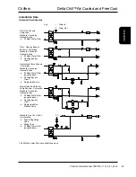
Please refer to the electrical wiring diagrams provided for installation.
ALL work MUST be carried out by technically trained competent personnel.
The equipment contains live electrical and moving parts, ISOLATE prior to maintenance or repair work.
General
As standard the equipment is designed for 400VAC, 3 phase, 3 wire 50Hz and a separate permanent 230VAC, 1 phase,
50Hz supply, to all relevant IEE regulations, British standards and IEC requirements
The control voltage to the interlocks is 24V AC, always size the low voltage interlock and protection cabling for a
maximum voltage drop of 2V
Avoid large voltage drops on cable runs, particularly low voltage wiring.
A fused and isolated electrical supply of the appropriate phase, frequency and voltage should be installed.
Wires should be capable of carrying the maximum load current under non-fault conditions at the stipulated voltage.
A separately fused, locally isolated, permanent single phase and neutral supply MUST BE FITTED for the compressor
oil heater, evaporator trace heating and control circuits, FAILURE to do so will INVALIDATE WARRANTY.
To reduce down time, if possible support the above supply with a UPS.
Ensure correct phase rotation.
Refrigeration
Before running the unit, all shut off valves must be opened. Any packaging must be carefully removed from coils.
The Emergency Stop MUST NOT be used to stop the chiller other than in the event of an
emergency.
CAUTION
The unit isolators DO NOT isolate the incoming mains supply, but isolate the individual electrical
panels.
Isolate REMOTELY the mains incoming supply to the BUSBAR chamber prior to maintenance or
repair work.
IMPORTANT
CAUTION
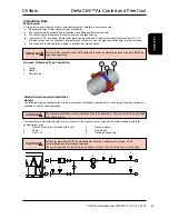
Please ensure the removal of the transport bracket prior to operating the compressors. Failure to
do so will invalidate warranty.

