


This feature will simple prevent overcurrent step pickup if the second-to-first harmonic
ratio in the measured current exceeds the set level.
Directional feature
M13751-263 v5
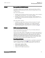
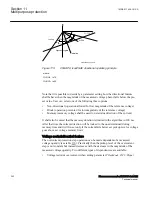
The overcurrent protection step operation can be made dependent on the relevant phase
angle between measured current phasor (see table
) and measured voltage phasor
). In protection terminology it means that the General currrent and
voltage protection (CVGAPC) function can be made directional by enabling this built-
in feature. In that case overcurrent protection step will only trip if the current flow is in
accordance with the set direction (
Forward
, which means towards the protected object,
or
Reverse
, which means from the protected object). For this feature it is of the outmost
importance to understand that the measured voltage phasor (see table
measured current phasor (see table
) will be used for directional decision. Therefore
it is the sole responsibility of the end user to select the appropriate current and voltage
signals in order to get a proper directional decision. CVGAPC function will NOT do
this automatically. It will simply use the current and voltage phasors selected by the
end user to check for the directional criteria.
Table
gives an overview of the typical choices (but not the only possible ones) for
these two quantities from traditional directional relays.
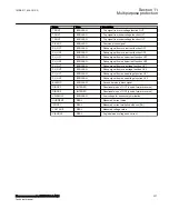
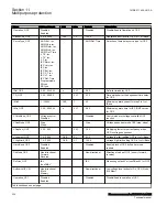
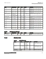
Table 192:
Typical current and voltage choices for directional feature
Set value for the
parameter
CurrentInput
Set value for the
parameter
VoltageInput
Comment
PosSeq
PosSeq
Directional positive sequence overcurrent function is
obtained. Typical setting for
RCADir is from 45° to 90°
depending on the power system voltage level (X/R ratio)
NegSeq
-NegSeq
Directional negative sequence overcurrent function is
obtained. Typical setting for
RCADir is from 45° to 90°
depending on the power system voltage level (X/R ratio)
3ZeroSeq
-3ZeroSeq
Directional zero sequence overcurrent function is
obtained. Typical setting for
RCADir is from 0° to 90°
depending on the power system grounding (that is, solidly
grounding, grounding via resistor)
Phase1
Phase2-Phase3
Directional overcurrent function for the first phase is
obtained. Typical setting for
RCADir is +30° or +45°
Phase2
Phase3-Phase1
Directional overcurrent function for the second phase is
obtained. Typical setting for
RCADir is +30° or +45°
Phase3
Phase1-Phase2
Directional overcurrent function for the third phase is
obtained. Typical setting for
RCADir is +30° or +45°
Unbalance current or voltage measurement shall not be used when the directional
feature is enabled.
Section 11
1MRK 511 408-UUS A
Multipurpose protection
340
Phasor measurement unit RES670 2.2 ANSI
Technical manual
Summary of Contents for Relion RES670
Page 1: ...RELION 670 SERIES Phasor measurement unit RES670 Version 2 2 ANSI Technical manual ...
Page 2: ......
Page 276: ...270 ...
Page 306: ...300 ...
Page 360: ...354 ...
Page 406: ...400 ...
Page 614: ...608 ...
Page 732: ...726 ...
Page 748: ...742 ...
Page 884: ...878 ...
Page 932: ...926 ...
Page 933: ...927 ...


