


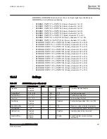


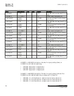


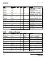


Name
Values (Range)
Unit
Step
Default
Description
MinRepIntVal6
0 - 3600
s
1
2
Minimum reporting interval input 6
MinRepIntVal7
0 - 3600
s
1
2
Minimum reporting interval input 7
MinRepIntVal8
0 - 3600
s
1
2
Minimum reporting interval input 8
MinRepIntVal9
0 - 3600
s
1
2
Minimum reporting interval input 9
MinRepIntVal10
0 - 3600
s
1
2
Minimum reporting interval input 10
MinRepIntVal11
0 - 3600
s
1
2
Minimum reporting interval input 11
MinRepIntVal12
0 - 3600
s
1
2
Minimum reporting interval input 12
MinRepIntVal13
0 - 3600
s
1
2
Minimum reporting interval input 13
MinRepIntVal14
0 - 3600
s
1
2
Minimum reporting interval input 14
MinRepIntVal15
0 - 3600
s
1
2
Minimum reporting interval input 15
MinRepIntVal16
0 - 3600
s
1
2
Minimum reporting interval input 16
16.5.6
Operation principle
M12807-6 v6
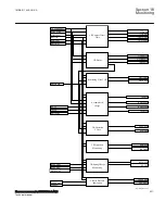
The main purpose of the Event function (EVENT) is to generate events when the state
or value of any of the connected input signals is in a state, or is undergoing a state
transition, for which event generation is enabled.
Each EVENT function has 16 inputs INPUT1 - INPUT16. Each input can be given a
name from the Application Configuration tool. The inputs are normally used to create
single events, but are also intended for double indication events. For double
indications, only the first eight inputs, 1–8, must be used. Inputs 9–16 can be used for
other types of events in the same EVENT block.
The EVENT function also has an input BLOCK to block the generation of events.
Events that are sent from the IED can originate from both internal logical signals and
binary input channels. The internal signals are time-tagged in the main processing
module, while the binary input channels are time-tagged directly on the input module.
Time-tagging of the events that are originated from internal logical signals have a
resolution corresponding to the execution cycle-time of the source application. Time-
tagging of the events that are originated from binary input signals have a resolution of
1 ms.
The outputs from the EVENT function are formed by the reading of status, events and
alarms by the station level on every single input. The user-defined name for each input
is intended to be used by the station level.
All events according to the event mask are stored in a buffer, which contains up to
1000 events. If new events appear before the oldest event in the buffer is read, the
oldest event is overwritten and an overflow alarm appears.
1MRK 511 408-UUS A
Section 16
Monitoring
Phasor measurement unit RES670 2.2 ANSI
551
Technical manual
Summary of Contents for Relion RES670
Page 1: ...RELION 670 SERIES Phasor measurement unit RES670 Version 2 2 ANSI Technical manual ...
Page 2: ......
Page 276: ...270 ...
Page 306: ...300 ...
Page 360: ...354 ...
Page 406: ...400 ...
Page 614: ...608 ...
Page 732: ...726 ...
Page 748: ...742 ...
Page 884: ...878 ...
Page 932: ...926 ...
Page 933: ...927 ...


