


Name
Values (Range)
Unit
Step
Default
Description
tBlkUV1
0.000 - 60.000
s
0.001
0.000
Time delay of internal (low level) blocking for
step 1
HystAbs1
0.0 - 50.0
%VB
0.1
0.5
Absolute hysteresis in % of VBase, step 1
OperationStep2
Disabled
Enabled
-
-
Enabled
Enable execution of step 2
Characterist2
Definite time
Inverse curve A
Inverse curve B
Prog. inv. curve
-
-
Definite time
Selection of time delay curve type for step 2
OpMode2
1 out of 3
2 out of 3
3 out of 3
-
-
1 out of 3
Number of phases required for op (1 of 3, 2 of
3, 3 of 3) from step 2
Pickup2
1.0 - 100.0
%VB
0.1
50.0
Voltage pickup value (Definite-Time &
Inverse-Time curve) in % of VBase, step 2
t2
0.000 - 60.000
s
0.001
5.000
Definitive time delay of step 2
t2Min
0.000 - 60.000
s
0.001
5.000
Minimum operate time for inverse curves for
step 2
TD2
0.05 - 1.10
-
0.01
0.05
Time multiplier for the inverse time delay for
step 2
IntBlkSel2
Disabled
Block of trip
Block all
-
-
Disabled
Internal (low level) blocking mode, step 2
IntBlkStVal2
1 - 50
%VB
1
20
Voltage setting for internal blocking in % of
VBase, step 2
tBlkUV2
0.000 - 60.000
s
0.001
0.000
Time delay of internal (low level) blocking for
step 2
HystAbs2
0.0 - 50.0
%VB
0.1
0.5
Absolute hysteresis in % of VBase, step 2
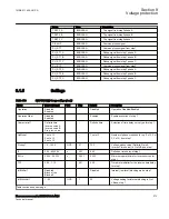
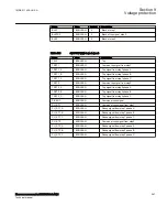
Table 151:
UV2PTUV (27) Group settings (advanced)
Name
Values (Range)
Unit
Step
Default
Description
tReset1
0.000 - 60.000
s
0.001
0.025
Reset time delay used in IEC Definite Time
curve step 1
ResetTypeCrv1
Instantaneous
Frozen timer
Linearly decreased
-
-
Instantaneous
Selection of used IDMT reset curve type for
step 1
tIReset1
0.000 - 60.000
s
0.001
0.025
Time delay in Inverse-Time reset (s), step 1
ACrv1
0.005 - 200.000
-
0.001
1.000
Parameter A for customer programmable
curve for step 1
BCrv1
0.50 - 100.00
-
0.01
1.00
Parameter B for customer programmable
curve for step 1
CCrv1
0.0 - 1.0
-
0.1
0.0
Parameter C for customer programmable
curve for step 1
DCrv1
0.000 - 60.000
-
0.001
0.000
Parameter D for customer programmable
curve for step 1
Table continues on next page
Section 9
1MRK 511 408-UUS A
Voltage protection
274
Phasor measurement unit RES670 2.2 ANSI
Technical manual
Summary of Contents for Relion RES670
Page 1: ...RELION 670 SERIES Phasor measurement unit RES670 Version 2 2 ANSI Technical manual ...
Page 2: ......
Page 276: ...270 ...
Page 306: ...300 ...
Page 360: ...354 ...
Page 406: ...400 ...
Page 614: ...608 ...
Page 732: ...726 ...
Page 748: ...742 ...
Page 884: ...878 ...
Page 932: ...926 ...
Page 933: ...927 ...