


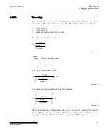

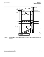


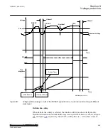


Pickup1
PU_ST1
TRST1
tReset1
t1
ANSI10000040-3-en.vsd
ANSI10000040 V3 EN-US
Figure 93:
Example for Definite Time Delay stage1 operation
9.1.7.3
Blocking
M15326-20 v8
It is possible to block Two step undervoltage protection UV2PTUV (27) partially or
completely, by binary input signals or by parameter settings, where:
BLOCK:
blocks all outputs
BLKTR1:
blocks all trip outputs of step 1
BLK1:
blocks all pickup and trip outputs related to step 1
BLKTR2:
blocks all trip outputs of step 2
BLK2:
blocks all pickup and trip outputs related to step 2
If the measured voltage level decreases below the setting of
IntBlkStVal1
, either the trip
output of step 1, or both the trip and the PICKUP outputs of step 1, are blocked. The
characteristic of the blocking is set by the
IntBlkSel1
parameter. This internal blocking
can also be set to
Disabled
resulting in no voltage based blocking. Corresponding
settings and functionality are valid also for step 2.
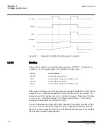
In case of disconnection of the high voltage component the measured voltage will get
very low. The event will PICKUP both the under voltage function and the blocking
function, as seen in figure
. The delay of the blocking function must be set less than
the time delay of under voltage function.
Section 9
1MRK 511 408-UUS A
Voltage protection
282
Phasor measurement unit RES670 2.2 ANSI
Technical manual
Summary of Contents for Relion RES670
Page 1: ...RELION 670 SERIES Phasor measurement unit RES670 Version 2 2 ANSI Technical manual ...
Page 2: ......
Page 276: ...270 ...
Page 306: ...300 ...
Page 360: ...354 ...
Page 406: ...400 ...
Page 614: ...608 ...
Page 732: ...726 ...
Page 748: ...742 ...
Page 884: ...878 ...
Page 932: ...926 ...
Page 933: ...927 ...


