


These signals shall be used for communication based ground-fault teleprotection
communication schemes (permissive or blocking).
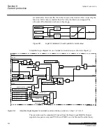
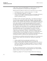
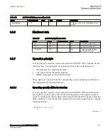
Simplified logic diagram for directional supervision element with integrated directional
comparison step is shown in Figure
:
X
a
a>b
b
IDirPU
polMethod=Voltage
polMethod=Dual
OR
FORWARD_Int
REVERSE_Int
BLOCK
STAGE1_DIR_Int
0.6
X
0.4
AND
STAGE3_DIR_Int
STAGE4_DIR_Int
STAGE2_DIR_Int
OR
PUREV
VPolMin
IPolMin
AngleRCA
T
F
0.0
X
T
F
RNPol
XNPol
0.0
D
ire
ct
io
na
l
C
ha
ra
ct
eri
st
ic
FWD
RVS
AND
AND
AND
PUFW
FORWARD_Int
REVERSE_Int
AND
ANSI07000067-4-en.vsd
|
|
VPol
VIPol
I3PDIR
VTPol
IopDir
Complex
Number
a
a>b
b
IPol
T
F
0.0
polMethod=Current
OR
ANSI07000067 V4 EN-US
Figure 61:
Simplified logic diagram for directional supervision element with integrated directional comparison
step
8.2.7.9
Second harmonic blocking element
M13941-200 v8
A harmonic restrain can be chosen for each step by a parameter setting
HarmBlockx
. If
the ratio of the 2nd harmonic component in relation to the fundamental frequency
component in the residual current exceeds the preset level (defined by parameter
1MRK 511 408-UUS A
Section 8
Current protection
Phasor measurement unit RES670 2.2 ANSI
207
Technical manual
Summary of Contents for Relion RES670
Page 1: ...RELION 670 SERIES Phasor measurement unit RES670 Version 2 2 ANSI Technical manual ...
Page 2: ......
Page 276: ...270 ...
Page 306: ...300 ...
Page 360: ...354 ...
Page 406: ...400 ...
Page 614: ...608 ...
Page 732: ...726 ...
Page 748: ...742 ...
Page 884: ...878 ...
Page 932: ...926 ...
Page 933: ...927 ...


