


•
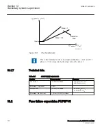
The change in voltage DV
•
The change in current DI
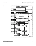
The internal
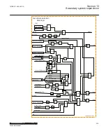
FuseFailDetDVDI
signal is activated if the following conditions are
fulfilled:
•
The magnitude of the phase-ground voltage has been above VPPU for more than
1.5 cycles (i.e. 30 ms in a 50 Hz system)
•
The magnitude of DV in three phases are higher than the corresponding setting
DVPU
•
The magnitudes of DI in three phases are below the setting DI<
In addition to the above conditions, at least one of the following conditions shall be
fulfilled in order to activate the internal
FuseFailDetDVDI
signal:
•
The magnitude of the phase currents in three phases are higher than the setting
IPPU
•
The circuit breaker is closed (52A = True)
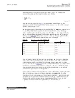
The first criterion means that detection of failure in three phases together with high
current for the three phases will set the output. The measured phase current is used to
reduce the risk of false fuse failure detection. If the current on the protected line is low,
a voltage drop in the system (not caused by fuse failure) may be followed by current
change lower than the setting DIPU, and therefore a false fuse failure might occur.
The second criterion requires that the delta condition shall be fulfilled at the same time
as circuit breaker is closed. If this is an important disadvantage, connect the 52A input
to FALSE , then only the first criterion can enable the delta function.If the DVDI
detection of three phases set the internal signal
FuseFailDetDVDI
at the level high,
then the signal
FuseFailDetDVDI
will remain high as long as the voltage of three
phases are lower then the setting VPPU.
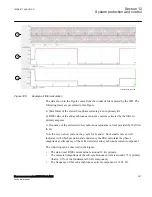
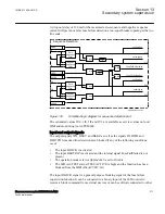
In addition to fuse failure detection, two internal signals
DeltaV
and
DeltaI
are also
generated by the delta current and delta voltage DVDI detection algorithm. The
internal signals
DelatV
and
DeltaI
are activated when a sudden change of voltage, or
respectively current, is detected. The detection of the sudden change is based on a
sample analysis algorithm. In particular
DelatV
is activated if at least three consecutive
voltage samples are higher then the setting
DVPU
. In a similar way
DelatI
is activated
if at least three consecutive current samples are higher then the setting
DIPU
.When
DeltaV
or
DeltaI
are active, the output signals PU_DV_A, PU_DV_B, PU_DV_C and
respectively PU_DI_A, PU_DI_B, PU_DI_C, based on a sudden change of voltage or
current detection, are activated with a 20 ms time off delay. The common pickup
output signals PU_DV or PU_DI are activated with a 60 ms time off delay, if any
sudden change of voltage or current is detected.
1MRK 511 408-UUS A
Section 13
Secondary system supervision
Phasor measurement unit RES670 2.2 ANSI
373
Technical manual
Summary of Contents for Relion RES670
Page 1: ...RELION 670 SERIES Phasor measurement unit RES670 Version 2 2 ANSI Technical manual ...
Page 2: ......
Page 276: ...270 ...
Page 306: ...300 ...
Page 360: ...354 ...
Page 406: ...400 ...
Page 614: ...608 ...
Page 732: ...726 ...
Page 748: ...742 ...
Page 884: ...878 ...
Page 932: ...926 ...
Page 933: ...927 ...


