


Set value:
Mode
Formula used for complex power calculation
CA
*
*
(
)
CA
C
A
S V
I
I
=
×
-
EQUATION2060-ANSI V1 EN-US
(Equation 33)
A
*
3
A
A
S
V
I
= ×
×
EQUATION2061-ANSI V1 EN-US
(Equation 34)
B
*
3
B
B
S
V
I
= ×
×
EQUATION2062-ANSI V1 EN-US
(Equation 35)
C
*
3
C
C
S
V
I
= ×
×
EQUATION2063-ANSI V1 EN-US
(Equation 36)
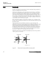
The active and reactive power is available from the function and can be used for
monitoring and fault recording.
The component of the complex power S = P + jQ in the direction
Angle1(2)
is
calculated. If this angle is 0° the active power component P is calculated. If this angle
is 90° the reactive power component Q is calculated.
The calculated power component is compared to the power pick up setting
Power1(2)
.
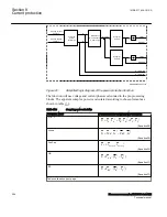
For directional underpower protection, a pickup signal PICKUP1(2) is activated if the
calculated power component is smaller than the pick up value. For directional
overpower protection, a pickup signal PICKUP1(2) is activated if the calculated power
component is larger than the pick up value. After a set time delay
TripDelay1(2)
a trip
TRIP1(2) signal is activated if the pickup signal is still active. At activation of any of
the two stages a common signal PICKUP will be activated. At trip from any of the two
stages also a common signal TRIP will be activated.
To avoid instability there is a settable hysteresis in the power function. The absolute
hysteresis of the stage1(2) is
Hysteresis1(2)
= abs
(Power1(2)
+ drop-power1(2)). For
generator low forward power protection the power setting is very low, normally down
to 0.02 p.u. of rated generator power. The hysteresis should therefore be set to a
smaller value. The drop-power value of stage1 can be calculated with
the Power1(2),
Hysteresis1(2)
: drop-power1(2) =
Power1(2)
+
Hysteresis1(2)
For small power1 values the hysteresis1 may not be too big, because the drop-
power1(2) would be too small. In such cases, the hysteresis1 greater than (0.5 ·
Power1(2)
) is corrected to the minimal value.
1MRK 511 408-UUS A
Section 8
Current protection
Phasor measurement unit RES670 2.2 ANSI
257
Technical manual
Summary of Contents for Relion RES670
Page 1: ...RELION 670 SERIES Phasor measurement unit RES670 Version 2 2 ANSI Technical manual ...
Page 2: ......
Page 276: ...270 ...
Page 306: ...300 ...
Page 360: ...354 ...
Page 406: ...400 ...
Page 614: ...608 ...
Page 732: ...726 ...
Page 748: ...742 ...
Page 884: ...878 ...
Page 932: ...926 ...
Page 933: ...927 ...


