


Set value for
parameter
“Mode”
Formula used for complex, three-
phase power calculation
Formula used for voltage and
current magnitude calculation
Comment
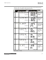
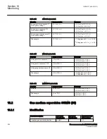
8
B
*
3
B
B
S
V I
= ×
×
EQUATION1575 V1 EN-US
(Equation 78)
3
B
B
V
V
I
I
=
×
=
EQUATION1576 V1 EN-US
(Equation 79)
Used when only
V
B
phase-to-
ground voltage is
available
9
C
*
3
C
C
S
V I
= ×
×
EQUATION1577 V1 EN-US
(Equation 80)
3
C
C
V
V
I
I
=
×
=
EQUATION1578 V1 EN-US
(Equation 81)
Used when only
V
C
phase-to-
ground voltage is
available
* means complex conjugated value
It shall be noted that only in the first two operating modes that is, 1 & 2 the
measurement function calculates the three-phase power accurately. In other operating
modes that is, from 3 to 9 it calculates the three-phase power under assumption that the
power system is fully symmetrical. Once the complex apparent power is calculated
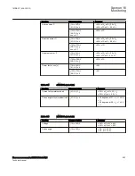
then the P, Q, S, & PF are calculated in accordance with the following formulas:
Re( )
=
P
S
EQUATION1403 V1 EN-US
(Equation 82)
Im( )
=
Q
S
EQUATION1404 V1 EN-US
(Equation 83)
2
2
=
=
+
S
S
P
Q
EQUATION1405 V1 EN-US
(Equation 84)
cos
P
PF
S
j
=
=
EQUATION1406 V1 EN-US
(Equation 85)
Additionally to the power factor value, the two binary output signals from the function
are provided which indicates the angular relationship between the current and voltage
phasors. Binary output signal ILAG is set TRUE when current phasor is lagging
behind voltage phasor. Binary output signal ILEAD is set TRUE when current phasor
is leading the voltage phasor.
Section 16
1MRK 511 408-UUS A
Monitoring
518
Phasor measurement unit RES670 2.2 ANSI
Technical manual
Summary of Contents for Relion RES670
Page 1: ...RELION 670 SERIES Phasor measurement unit RES670 Version 2 2 ANSI Technical manual ...
Page 2: ......
Page 276: ...270 ...
Page 306: ...300 ...
Page 360: ...354 ...
Page 406: ...400 ...
Page 614: ...608 ...
Page 732: ...726 ...
Page 748: ...742 ...
Page 884: ...878 ...
Page 932: ...926 ...
Page 933: ...927 ...


