

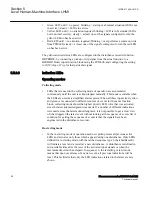


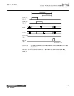


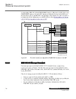


Note that the third positive edge on the input attribute does not cause a pulse, since the
edge was applied during pulse output. A new pulse can only begin when the output is
zero; else the trigger edge is lost.
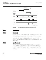
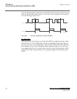
500ms
500ms
500ms
pulse time
pulse time
pulse time
500ms
IEC09000332_2_en.vsd
Input value
Output value
IEC09000332 V2 EN-US
Figure 29:
Sequence diagram for setting PULSED
Input function
GUID-8EA4AE21-7A74-403A-84AE-D5CEF9292A63 v2
All function keys work the same way: When the LHMI is configured so that a certain
function button is of type CONTROL, then the corresponding input on this function
block becomes active, and will light the yellow function button LED when high. This
functionality is active even if the function block operation setting is set to off. It has
been implemented this way for safety reasons; the idea is that the function key LEDs
should always reflect the actual status of any primary equipment monitored by these
LEDs.
Section 5
1MRK 511 408-UUS A
Local Human-Machine-Interface LHMI
102
Phasor measurement unit RES670 2.2 ANSI
Technical manual
Summary of Contents for Relion RES670
Page 1: ...RELION 670 SERIES Phasor measurement unit RES670 Version 2 2 ANSI Technical manual ...
Page 2: ......
Page 276: ...270 ...
Page 306: ...300 ...
Page 360: ...354 ...
Page 406: ...400 ...
Page 614: ...608 ...
Page 732: ...726 ...
Page 748: ...742 ...
Page 884: ...878 ...
Page 932: ...926 ...
Page 933: ...927 ...


