background image

User Manual 


IMPORTANT 
READ CAREFULLY BEFORE USE 
READ USER MANUAL FOR OPTIONAL PRODUCTS IF APPLICABLE 
KEEP FOR FUTURE REFERENCE 


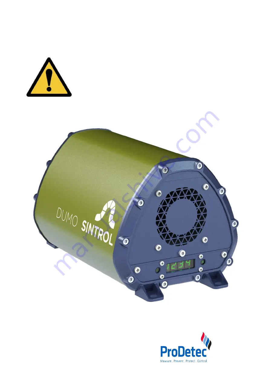
Dumo and Dumo RF 

 
Date: 11

th

 November 2019 

Version: 2.0 


ProDetec Pty.Ltd.

P.

    +61 (02) 9620 8700

F.     

+61 (02) 9620 8755

E.    

[email protected]

A. 

  17/38 Powers Rd,

      Seven Hills NSW 2147


www.prodetec.com.au

Summary of Contents for Sintrol Dumo

Page 1: ...R MANUAL FOR OPTIONAL PRODUCTS IF APPLICABLE KEEP FOR FUTURE REFERENCE Dumo and Dumo RF Date 11th November 2019 Version 2 0 ProDetec Pty Ltd P 61 02 9620 8700 F 61 02 9620 8755 E info prodetec com au A 17 38 Powers Rd Seven Hills NSW 2147 www prodetec com au ...

Page 2: ...justable installation arm 13 5 Principle of operation physical effects and limitations 14 5 1 Influence of particle material 14 5 2 Particle size 15 5 3 Linearity maximum concentrations and calibration 15 5 4 Influence of relative humidity RH condensation and droplets in the measurement gas 15 5 5 Influence of ambient temperature 15 5 6 Influence of flow velocity at the Dumo 16 6 Mechanical Instal...

Page 3: ...y Intercept a Integer 99 099 mg m3 33 8 5 10 Parameter 12 Display Intercept a Decimal 000 999 mg m3 34 8 5 11 Parameter 13 Display Slope b Integer 000 999 mg m3 mA 34 8 5 12 Parameter 14 Display Slope b Decimal 000 999 mg m3 mA 34 8 5 13 Parameter 15 20 mA scaling in 000 999 IEU x 1 000 000 34 8 5 14 Parameter 16 20 mA scaling in 000 999 IEU x 1 000 34 8 5 15 Info Firmware Version 34 9 Sintrol Dus...

Page 4: ... 18 Figure 11 Connecting power input 20 Figure 12 Connecting Relays 21 Figure 13 mA loop connection 22 Figure 14 RS485 connections 23 Figure 15 Connecting a RS485 Network 24 Figure 16 Settings after Auto setup 27 Figure 17 Front view of display 28 Figure 18 Bottom view of buttons 28 Figure 19 Example for display calibration 33 Figure 20 DustTool main window 36 Figure 21 Sintrol Network Example 38 ...

Page 5: ...r individual parts are damaged If this is the case do not use the instrument and contact the Sintrol Customer Service Department 1 3 Overview of the life cycle operation After unpacking the instrument the whole life cycle operation shall be handled as follows Choose the appropriate installation location see chapter 6 Mechanical Installation Install the instrument mechanically see chapter 6 Mechani...

Page 6: ...inor or moderate injury if not avoided This signal word warns of possible damage to property This symbol provides you with useful additional information on handling and use Label for waste materials intended for recycling Electrical products may not be disposed of with household or other garbage Applicable in the European Union and other European countries with separate collection systems of recyc...

Page 7: ...clusively designed to continuously measure the concentration of total suspended particles TSP in ambient air under the conditions and limits outlined in this manual It is primarily meant for indoor operation in non condensing conditions The instrument will recognize droplets as particles and therefore cannot distinguish between water droplets and dust It is ideal for applications where any disrupt...

Page 8: ...here are many factors which may influence the functionality of a dust measurement system These factors include but are not limited to the particle size of the dust the dust material design and maintenance of ductwork as well as worker procedure and error Therefore the statements made in Chapter3 Intended use do not automatically imply the fitness of any of the Products for a particular installatio...

Page 9: ...vel is determined and the two Alert and Alarm levels are defined to factor five and factor 20 of that level The instrument can also be calibrated to show mg m3 by performing a reference measurement The instrument has a built in fan which draws in a steady and constant flow of ambient air through the measuring chamber Particulate flowing through the chamber will interact with the sensor rod causing...

Page 10: ...tion to ensure identical instruments and quality X X Linearized during production to standard test dust Arizona Road Dust X X RS485 to communicate with Modbus RTU to your control system or with Sintrol protocol to your PC and DustTool X X All possibly contaminated parts are easy to clean X X Bright green illuminated 4 digit display and buttons for local setup and status X X Isolated and active mA ...

Page 11: ...n options Standard Built in mounting feet for wall ceiling or tabletop mounting Option Wall DIN rail mount bracket Option Adjustable installation arm The standard built in mounting feet is the most suitable choice for installations with high vibrations Power supply Sintrol has thoroughly tested and can recommend the following power supplies to be used Option XP DNR120AS24 DIN rail mount into cabin...

Page 12: ...cable glands capable of accepting cable diameters between 4 5 and 10 mm 4 5 Terminal cover on the underside of the Dumo On the underside of the device is a terminal cover with an O ring This is used to secure the device electronics and the terminals The screw plug must be opened for electrical installation and should then be tightened and closed with 30Nm Terminal cover 35 mm or 60 mm two hole key...

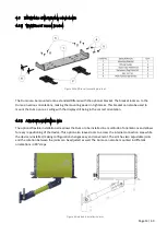
Page 13: ...e display still being in the correct orientation 4 6 2 Adjustable installation arm The optional flexible installation arm allows the Dumo to be installed in a multitude of orientations and allows for easy repositioning of the device This option also leaves room to access the internal connection area while the device is installed making configuration changes easy and convenient The arm has two adju...

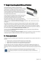
Page 14: ...s charge is captured by our sensor and its signal level is proportional to the particle concentration As a unit for this signal level the Inductive Electrification Unit IEU is used The relation between Inductive Electrification Unit IEU and the mA output signal can be established by performing the Auto Setup function The relation between Inductive Electrification Unit IEU and the dust concentratio...

Page 15: ...Nonlinear range from linear phase up to several g m3 Saturation after nonlinear range Figure 6 Illustration of un calibrated measuring behavior To measure higher concentrations than 200 mg m3 and it is critical to have a linear behaviour we recommend performing reference measurements at the desired concentration and add additional calibration points by using Sintrol DustTool calibration 5 4 Influe...

Page 16: ...quipped with an internal sampling fan which provides a constant flow speed The fan is also monitored for changes in the performance to ensure a constant flow speed In situations with high winds 5m s the surrounding airflow may affect the internal flow speed of the Dumo and decrease the accuracy of the measurement ...

Page 17: ...the device with different mounting hardware including Wall Din rail mount bracket or the adjustable wall connecting system For installations with the RF version make sure that all the Dumos are oriented in the same direction antenna pointing in the same direction vertical or horizontal in order to avoid polarization losses in the wireless communication 6 1 Height In ambient air larger airborne par...

Page 18: ... directly at the source point may have already reached the minimum explosible concentration MEC it may be well below this critical level further away The time delay between the appearance of the dust at its source point and the measuring point will be longer and the movement of the dust cloud slower the further away the two points are from each other Figure 9 Installation Point in terms of air flo...

Page 19: ...you are not using it when you intend to clean it or in the event of a malfunction Only connect the Dumo if the line voltage of the socket corresponds to the data on the rating plate Stand on an insulating pad and make it a habit to only use one hand when checking components Always work with another person in case an emergency should occur Disconnect power before checking the Dumo or performing mai...

Page 20: ...he Dumo external grounding terminal is connected to a nearby grounding strip Telltale signs of improper grounding include base values of over 3000 in clean office air or noticeable reaction to touching the Dumo series enclosure Note that sub par quality power sources might also induce such effects 7 1 Connecting the voltage supply Figure 11 Connecting power input Connect a 24 VDC power supply to t...

Page 21: ...ipment provided that the USB port has the capability to provide enough energy The USB port is a Micro USB type B inside of the enclosure in the connection area behind the threaded plug USB is intended to be used for easy parameterization of Sintrol products with dedicated complementary DustTool software However the USB is not suitable to operate or substitute a dedicated industrial bus and it is n...

Page 22: ...t can also be customized according to the end user application An mA output loop is intended to be used as a long range analog data transfer in industrial environments The signal output is isolated to shield against local potential differences between the two end locations The device will also alarm on the mA output for device failures according to NAMUR NE 43 mA output State 4 20 mA Normal measur...

Page 23: ...introl Network and Modbus RTU RS485 bus can be used to connect the Dumo to the customers own automation systems with the industry standard Modbus RTU protocol This interface can be used to read data from the Dumo as well as change measurement parameters Dumo has an isolated RS485 bus which can be selected to operate in Sintrol Network protocol for connections to DustTool or DustLog software or wit...

Page 24: ...Use suitable 3 wire or above shielded cabling minimum 0 3 mm2 or AWG 22 and make sure to ground the shield at a single location Figure 15 Connecting a RS485 Network Make sure that the RS485 bus terminator resistor switch is enabled only on the last device in the bus Using DustTool confirm on the properties page that the RS485 protocol is set appropriately To use the device with a Modbus RTU master...

Page 25: ...alid measurement signal The measurement signal is below the configured trash hold for the ALERT or ALARM status ALERT The instrument operates normally as it has been stetted up and gives a valid measurement signal The measurement signal is above the configured trash hold for the ALERT status default 5 times the Auto setup dust level but below the ALARM status ALARM The instrument operates normally...

Page 26: ...s orange on According to Dust level ALARM off on on According to Dust level AUTO SETUP blink off count down s MAINTENANCE blink alternating with red 500ms blink alternating with green 500ms conditional to diagnostic code FAULT INDICATION off blink alternating left and right with interval 500ms conditional to diagnostic code or Table 2 LED and Display functional logic ...

Page 27: ...ust level during auto setup In addition the following key parameters will also be affected 4 mA equals no dust present 20 mA is set to 20 times the dust level during auto setup Dust signal averaging time is set to default 50 seconds Signal delay times are set to default 30 seconds In other words Baseline will be set to 5 of range or 4 8mA ALERT Relay 1 will switch at 25 of range or at 8mA ALARM Re...

Page 28: ...tons In normal operation the instrument will show the measurement value When is pressed the instrument goes to the parameter display change mode The cursor position is indicated with a blinking number To increment the value of the blinking number press To shift the cursor to the right press To save the changed parameter press տ After saving the changed parameter will come into effect and the curso...

Page 29: ...an be set to operate either with customer selectable parameters or in one of pre determined modes These modes change the behavior of the Dumo making the response either SLOW MEDIUM or FAST The display shows periodically which of the parameter sets is in use or CUST if custom settings have been selected by modifying the parameters manually Parameter SLOW MEDIUM default FAST Param 2 Averaging time s...

Page 30: ...D3 1 mA x x D3 2 mg m3 shows if mg m3 is disabled x 2 Averaging time sec 000 300 sec default 50 sec x x 3 20 mA scaling Range setting 000 999 default 100 determined by the value after Auto setup 20 times Baseline x x 4 Alarm limit A of Range 000 100 of Range default 25 of Range 8mA x x 5 Alarm limit B of Range 000 100 of Range default 100 of Range 20mA x x 6 Alarm delay time sec 000 180 sec defaul...

Page 31: ...sted to be 20 times the dust level present during the period automatic setup was running This level represents 100 of Range 20mA To manually half the Alarm limit B Set Parameter 5 to be 050 of Range The parameters 3 and 5 are independent If you double the Range with Parameter 3 the alarm limit B will stay at the same level and Parameter 5 will show half the value 50 of Range 8 5 6 Parameter 6 Alar...

Page 32: ... done settings will be over written To show on the local display the measurement in mg m3 follow the below procedure Enter the definition of the calibration function yi a b xi by changing the parameters 1 2 3 and 4 Navigate to Parameter 10 by pressing K1 Key 002 into the instrument Safe the result by pressing K3 Navigate to Parameter 1 by pressing K1 Key 002 into the instrument Safe the result by ...

Page 33: ...Par 13 14 x Result of AMS mA Example calculation yi mg m3 xi mA Comment Point 1 6 00 9 00 In a simple one point calibration 4 mA would equal 0 mg m3 Point 2 19 00 17 00 Result of the gravimetric sampling 1 Calculate the slope b by the two point form of a straight line b y2 y1 x2 x1 In our case b 19 00 6 00 17 00 9 00 1 625 2 Resolve the equation yi a b xi to the intercept a a yi b xi 3 Calculate t...

Page 34: ... IEU value at the Parameters 15 and 16 is the base for the Range setting on the Sintrol Signal Generator The Signal Generator is used for the linearity checks in regulated applications As the IEU is a very fine scale with an open scale from 0 to several millions the reading of this number is split into two parameters Parameter 15 20 mA scaling in 000 999 IEU x 1 000 000 Parameter 16 20 mA scaling ...

Page 35: ...d auto setup is disabled and changing any device parameters will not be allowed If the lock password is forgotten there is no way to unlock the device without contacting Sintrol for the device specific master password When DustTool software opens it first looks for USB connected Sintrol products If any are connected they will appear within the software and can then be directly managed A DustTool v...

Page 36: ...he changes into the memory of the instrument If the Save button is not pressed the changes will not be sent to the device and the values will be lost at program shut down or when the instrument is detached 3 By pressing Read the parameters which are currently saved in the instrument will be loaded from the device In the MONITOR tab of the DustTool software it is possible to follow dust levels onli...

Page 37: ...complete Sintrol Network based measurement system consists of up to 254 instruments on a single network connected either wirelessly or with an RS485 bus to the data collecting and reporting software DustLog 8 The basic principle and topology are shown in the figure above Sintrol Wireless solution is part of the whole Sintrol Network system For this reason the wireless RF connection can operate tra...

Page 38: ...ignals into the radio network and back The base station can also be connected to a PC via USB where it is then possible to run Sintrol DustLog 8 data collection software to manage and operate the network online Sintrol Network products operate automatically as repeaters within the network therefore repeaters are rarely needed This device is not covered by this manual please read and follow the res...

Page 39: ...ove the front cover of the Dumo and clean the probe with compressed air a fabric or if necessary a brush Remove the rear cover of the Dumo and clean the fan with compressed air a fabric or if necessary a brush Perform a bump test by applying an unusual amount of dust to the sensor and observe that it will react Risk of malfunction for critical installations where malfunctions may lead to dangerous...

Page 40: ...cleaned with soft brushes and mild solvents should the dust be stuck on If the Dumo is with the optional PTFE coated probe do not use any abrasive cleaning methods 5 Close the cover with the screws removed in section 1 Make sure that the short internal duct section does not fall of Tighten the screws to max 7 Nm If you have a Teflon coated probe avoid using any other tools than fabrics for cleanin...

Page 41: ... warranty 1 Disconnect power to the Dumo 2 Remove the rear cover by removing these 5 screws Figure 24 Removing the rear cover 3 Disconnect the fan cable The connector is locked into place with a threaded locking ring which can be loosened by turning it counter clockwise with needle nose pliers Figure 25 Replacing the fan 4 Install the new fan Make sure to properly tighten the connector locking rin...

Page 42: ...uto setup If the Dumo is not giving an output signal after these checks contact your local distributor 12 2 No response after auto setup Make sure that normal processes are going on during auto setup Check that the power and signal wiring are connected correctly If the Dumo is not giving an output signal after these checks contact your local distributor ...

Page 43: ...e Default at factory 100 s Adjustable from 0 6000 s Alarm delay time Default at factory 30 s Adjustable from 0 60 000 s Alarm hysteresis time Default at factory 0 s Adjustable from 0 25 s Ambient Conditions Running temperature 40 C to 60 C 40 F to 140 F Humidity Max 95 RH non condensing Materials and Dimensions Enclosure housing Aluminum enclosure stainless steel cover plates and probe AISI 316L W...

Page 44: ...t distributors The maintenance and service of instruments sold in Finland Russia Ukraine Kazakhstan India and China are managed by Sintrol s subsidiaries and representative offices The contact details are found below The original language of this user manual is English United States It is the responsibility of Sintrol s local subsidiaries representative offices or distributers to provide a proper ...

Page 45: ...Page 45 49 15 Appendix 15 1 ISO 9001 certificate ...

Page 46: ...Page 46 49 15 2 MODBUS RTU register map ...

Page 47: ...Page 47 49 ...

Page 48: ...Page 48 49 ...

Page 49: ...cling information applies to local regulations and the EPA recommendations www epa gov 17 Notes 18 Acknowledgements Sintrol Oy Ruosilantie 15 FI 00390 Helsinki Finland VAT number FI21439063 Registered domicile Helsinki Phone 358 9 5617 360 Fax 358 9 5617 3680 E mail info sintrol com www sintrolproducts com Duplication reproduction and translation as well as any commercial exploitation including ex...

Reviews: