background image

ELEC

ES

D

F

CHAPITRE 8

CIRCUIT

ELECTRIQUE

COMPOSANTS ELECTRIQUES .............8-1

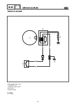
SCHEMA DE CABLAGE ..........................8-2

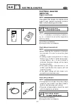
ANALYSE ELECTRIQUE ........................8-3

INSPECTION ...........................................8-3

Multimètre numérique ..........................8-3
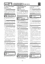
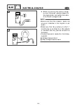
Mesure de la tension de crête ...............8-3
Adaptateur de tension de crête..............8-3

SYSTEME D’ALLUMAGE .......................8-5

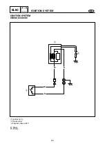
SCHEMA DE CABLAGE........................8-5
ELEMENTS POUR L’ENTRETIEN .......8-6

ECARTEMENT DES
ELECTRODES.....................................8-6
TENSION DE CRETE DU SYSTEME

D’ALLUMAGE..................................8-7

Resistencia de la bobina del conjunto 

del dispositivo de encendido...............8-7

BOUGIE ...............................................8-8
CAPUCHON DE BOUGIE..................8-8
COUPE-CIRCUIT DE SECURITE .....8-9

KAPITEL 8

ELEKTROANLAGE

ELEKTRIKKOMPONENTEN

.......................8-1

STROMLAUFPLAN

....................................8-2

ELEKTROSPEZIFISCHE
UNTERSUCHUNG

......................................8-3

INSPEKTION ..........................................8-3

Digitaler Stromkreisprüfer................8-3
Messung der Spitzenspannung .......8-3
Spitzenspannungsadapter................8-3

ZÜNDANLAGE

...........................................8-5

STROMLAUFPLAN ................................8-5
WARTUNGSPUNKTE ............................8-6

FUNKENSCHLAGWEITE ...................8-6
SPITZENSPANNUNG DER

ZÜNDANLAGE ................................8-7

Widerstand der Zündspule...............8-7
ZÜNDKERZE ......................................8-8
ZÜNDKERZENELEKTRODEN-

ABSTAND ........................................8-8

MOTORSTOPPSCHALTER................8-9

CAPITULO 8

SISTEMA ELECTRICO

COMPONENTES ELECTRICOS.............8-1

DIAGRAMA DE CABLEADO ..................8-2

ANALISIS ELECTRICO ...........................8-3

INSPECCION ...........................................8-3

Comprobador de circuitos digitales ......8-3
Medida de la tensión máxima ...............8-3
Adaptador de tensión máxima ..............8-3

SISTEMA DE ENCENDIDO .....................8-5

DIAGRAMA DE CABLEADO................8-5
PUNTOS DE SERVICIO .........................8-6

DISTANCIA ENTRE ELECTRODOS

DE BUJIA DE ENCENDIDO ............8-6

TENSION MAXIMA DEL SISTEMA

DE ENCENDIDO...............................8-7

Resistencia de la bobina del conjunto 

del dispositivo de encendido...............8-7

BUJIA ...................................................8-8
TAPA DE LA BUJÍA...........................8-8
INTERRUPTOR DE PARADA DEL

MOTOR..............................................8-9

8

Содержание F4

Страница 1: ...p Marine Outboards F4A 290333 WORLD WIDE F4 USA CANADA SERVICE MANUAL MANUEL D ENTRETIEN WARTUNGSANLEITUNG MANUAL DE SERVICIO E F D ES ...

Страница 2: ...mechanics when performing maintenance procedures and repairs to Yamaha equipment It has been written to suit the needs of persons who have a basic understanding of the mechanical and electrical concepts and procedures inherent in the work for without such knowledge attempted repairs or service to the equipment could render it unsafe or unfit for use Because the Yamaha Motor Company Ltd has a polic...

Страница 3: ...unos conocimien tos básicos de los conceptos y procedi mientos mecánicos y eléctricos inhe rentes a dichos trabajos de manteni miento y reparación ya que de no po seer tales conocimientos las posibles reparaciones o mantenimiento del equipo podrían afectar adversamente su seguridad y operatividad Puesto que Yamaha Motor Company Ltd sigue una política de mejora conti nua de sus productos puede que ...

Страница 4: ...evised format the condition of a faulty component will precede an arrow symbol and the course of action required will follow the symbol e g 8 Bearings Pitting Scratches Replace To assist you to find your way through this manual the section title and major heading is given at the top of every page ILLUSTRATIONS The illustrations within this service manual represent all of the designated models CROS...

Страница 5: ...erlichen Maßnahmen werden nach dem Symbol beschrieben z B 9 Lager Lochfraß Beschädigung Ersetzen Um Ihnen das Auffinden von ge wünschten Stellen in dem Hand buch zu erleichtern ist oben auf je der Seite der Titel des Kapitels und betreffenden Abschnitts aufgeführt ABBILDUNGEN Die Abbildungen in diesem Kun dendiensthandbuch beziehen sich auf alle Modelle QUERVERWEISE Querverweise sind auf ein Minde...

Страница 6: ...T YOUR SAFETY IS INVOLVED w Failure to follow WARNING instructions could result in severe injury or death to the machine operator a bystander or a person inspecting or repairing the outboard motor cC A CAUTION indicates special precautions that must be taken to avoid damage to the out board motor NOTE A NOTE provides key information to make procedures easier or clearer E ...

Страница 7: ...EU XG Le respect des consignes AVERTISSEMENT est impératif faute de quoi le conducteur toute personne se trouvant à proximité ou le personnel chargé de l entretien du moteur hors bord risquerait d être grièvement voire mortellement bles sé fF ATTENTION indique les consignes qui doivent être respectées afin d éviter d endommager le moteur hors bord N B N B donne des informations importantes qui fac...

Страница 8: ...ES GEHT UM IHRE SICHERHEIT W Ein Nichtbefolgen der Warnhinweise kann ernsthafte Verletzungen und sogar den Tod zur Folge haben Dies gilt für Be diener Zuschauer und am Motor arbeitende Techniker gleichermaßen dD DUnter dieser Überschrift ergehen Hinweise auf Vorsichtsmaßnahmen zum Schutze des Motors HINWEIS Hier geht es um nützliche Tips und Hinweise D ...

Страница 9: ...ervancia de las instrucciones contenidas en un AVISO puede provocar graves lesiones o incluso la muerte del operador del motor fuera borda de las personas que se encuentren a su alrededor o de la persona que inspeccione o repare el motor fuera borda bB Una PRECAUCION indica cuidados especiales que deben tomarse para evitar dañar el motor fuera borda NOTA Una NOTA ofrece información clave para faci...

Страница 10: ... lb 1st 3 Nm 0 3 m kg 2 17 ft lb 2nd 8 Nm 0 8 m kg 5 8 ft lb 6 1 REMOVAL AND INSTALLATION CHART Step 1 2 3 4 5 6 7 8 9 10 Q ty 1 1 1 1 1 1 1 1 1 1 Service points Follow the left Step for removal NOTE Set the shift lever to reverse position and loosen the bolt shift rod connec tor Not reusable Procedure Part name LOWER UNIT REMOVAL Cotter pin Propeller nut Washer Propeller Spacer Bolt anode Toothed...

Страница 11: ...t siehe SYMBOLE 4 Eine Tabelle mit Anweisungen in der die Reihenfolge der Ar beitsschritte die Bezeichnungen der Teile Anmerkungen zu den Arbeitsschritten usw erwähnt werden ist jeder Darstellung in aufgelösten Einzelteilen hinzu gefügt Beispiel O Ring Größe 39 5 2 5 mm Innendurchmesser D Ring durchmesser d 5 Bei Befestigungsteilen die mit auf ein bestimmtes Moment an gezogen werden müssen sind di...

Страница 12: ...sistance Voltage V Electric current A Symbol y to o in an exploded diagram in dicate the grade of lubricant and location of the lubrication point y Apply Yamaha 4 stroke outboard motor oil u Apply molybdenum disulfide oil i Apply water resistant grease Yamaha grease A Yamaha marine grease o Apply molybdenum disulfide grease Symbols p to f in an exploded diagram indicate grade of sealing or locking...

Страница 13: ... Stromstärke A Die Symbole y bis o in einer Dar stellung in aufgelösten Einzelteilen weisen auf den Schmiermittelgrad und Schmierstellen hin y Yamaha Viertakt Außenbordmotoröl benutzen u Molybden Disulfid Öl auftragen i Wasserbeständiges Fett Yamaha Schmierfett A Yamaha Marinefett benutzen o Molybden Disulfid Fett auftragen Die Symbole p bis f in einer Dar stellung in aufgelösten Einzelteilen weis...

Страница 14: ...E TROUBLE ANALYSIS A30000 0 INDEX FUEL SYSTEM POWER UNIT LOWER UNIT BRACKET UNIT ELECTRICAL SYSTEM PERIODIC INSPECTION AND ADJUSTMENT SPECIFICATION GENERAL INFORMATION ...

Страница 15: ...TECHNISCHE DATEN REGELMÄSSIGE WARTUNG UND EIN STELLUNGEN 4 SISTEMA DE COMBUSTIBLE FUEL CIRCUIT D ALI MENTATION KRAFTSTOFFAN LAGE 5 MOTOR POWR MOTEUR STROMVER SORGUNG 6 UNIDAD INFERIOR LOWR BOITIER D HE LICE UNTERER TEIL 7 UNIDAD DE SOPORTE BRKT SUPPORT HALTERUNGSRAH MEN 8 SISTEMA ELECTRICO ELEC CIRCUIT ELECTRIQUE ELEKTROANLAGE PROBLEMLÖSUN GEN TABLE DES MATIERES INHALT INDICE GEN INFO INFORMATIONS...

Страница 16: ...ING SERIAL NUMBERS 1 1 SAFETY WHILE WORKING 1 2 FIRE PREVENTION 1 2 VENTILATION 1 2 SELF PROTECTION 1 2 OILS GREASES AND SEALING FLUIDS 1 2 GOOD WORKING PRACTICES 1 3 DISASSEMBLY AND ASSEMBLY 1 4 SPECIAL TOOLS 1 5 MEASURING 1 5 REMOVAL AND INSTALLATION 1 6 HANDLING PRECAUTIONS 1 9 E ...

Страница 17: ...SNUMMERN DER SERIE 1 1 SICHERHEITSMASSNAHMEN 1 2 BRANDSCHUTZ 1 2 BELÜFTUNG 1 2 SELBSTSCHUTZ 1 2 ÖLE SCHMIERSTOFFE UND DICHTUNGSMITTEL 1 2 RICHTIGE ARBEITSGEWOHNHEITEN 1 3 DEMONTAGE UND MONTAGE 1 4 SPEZIALWERKZEUGE 1 5 MESSEN 1 5 AUSBAU UND EINBAU 1 6 VORKEHRUNGSMASSNAHMEN 1 9 CAPITULO 1 INFORMACION GENERAL IDENTIFICACION 1 1 NUMERO DE SERIE 1 1 NUMEROS INICIALES DE SERIE 1 1 SEGURIDAD EN EL TRABAJ...

Страница 18: ...mber is stamped is bonded to the port side of the clamp bracket The label is specially treated so that peeling it off causes cranks across the serial number 1 Model name 2 Approved model code 3 Transom height 4 Serial number YAMAHA MOTOR CO LTD MADE IN JAPAN PAYS D ORIGINE JAPON 1 2 3 4 E Model name World wide USA CANADA STARTING SERIAL NUMBERS The starting serial number blocks are as follows F4AM...

Страница 19: ...sse an der Seriennummer entstehen 1 Modellbezeichnung 2 Zugelassene Modellnummer 3 Spiegelhöhe 4 Seriennummer ANFANGSNUMMERN DER SERIE Die Anfangsnummern der Serien sind wie folgt IDENTIFICACION NUMERO DE SERIE El número de serie del motor fuera borda aparece estampado en la etiqueta fijada al lado de babor de la abrazadera de sujeción NOTA Como medida antirrobo al lado de ba bor del soporte de ab...

Страница 20: ...eum vapor is heavier than air and is deadly if inhaled in large quantities Engine exhaust gases are harmful to breathe When test running an engine indoors maintain good ventilation SELF PROTECTION Protect your eyes with suitable safety glasses or safety goggles when grinding or when doing any operation which may cause particles to fly off Protect hands and feet by warning safety gloves or protecti...

Страница 21: ...n sowie Funken und offenes Feuer vermeiden BELÜFTUNG Benzindämpfe sind schwerer als Luft Bei Einatmung großer Mengen besteht Lebensgefahr Motorabga se sind gesundheitsschädlich und bei längerem Einatmen lebensge fährlich Beim Probelauf eines Mo tors in geschlossenen Räumen für ausreichende Belüftung sorgen SELBSTSCHUTZ Beim Arbeiten mit Druckluft bei Schleifarbeiten oder bei Spritzge fahr eine gee...

Страница 22: ...soiled wiping rag in your pocket 4 Hands and any other part of the body which have been in contact with lubri cants or lubricant contaminated cloth ing should be thoroughly washed with hot water and soap as soon as practica ble 5 To protect the skin the application of a suitable barrier cream to the hands before working is recommended 6 A supply of clean lint free cloths should be available for wi...

Страница 23: ...so el empleo de los lubricantes mencionados en este manual no debe plantear nin gún riesgo pero la seguridad es un tema de la máxima importancia por lo que la adopción de algunas medidas de seguridad puede reducir los posibles riesgos A continuación se incluye un resumen de las precauciones más importantes 1 Cuando trabaje mantenga una hi giene personal e industrial correc ta 2 La ropa contaminada...

Страница 24: ...Oil the contact surfaces of moving parts before assembly 3 After assembly check that moving parts operate normally 4 Install bearings with the manufacturer s markings on the side exposed to view and liberally oil the bearings cC Do not use compressed air to spin the bearing dry This cause damage to the bearings surfaces 5 When installing oil seals apply a light coating of water resistant grease to...

Страница 25: ...ile mit Druckluft reinigen 2 Kontaktflächen beweglicher Teile beim Einbau fetten 3 Nach der Montage bewegliche Teile auf einwandfreie Funktion prüfen 4 Lager so einsetzen daß die Herstellerkennzeichen sichtbar sind Lager ausreichend fetten dD Lager niemals mit Druckluft säu bern Die Lagerlaufflächen könnten beschädigt werden 5 Beim Einbau der Öldichtungen diese leicht mit einem wasser beständigen ...

Страница 26: ...0890 MEASURING 1 Tachometer a P N YU 08036 A b 90890 06760 2 Leakage tester P N YB 03595 90890 06762 3 Digital calliper P N N A 90890 06704 4 Dial gauge set P N YU 03097 90890 01252 5 Digital circuit tester a P N J 39299 b 90890 06752 6 Spark gap tester a P N YM 34487 b 90890 06754 7 Test propeller P N YB 01630 90890 01630 8 Timing light P N YU 33277 A 90890 03141 9 Compression gauge P N YU 33223 ...

Страница 27: ...begin nende Teilenummer 9 Für andere Länder beziehen Sie sich auf die mit 90890 begin nende Teilenummer MESSEN 1 Drehzahlmesser a Best nr YU 08036 A b 90890 06760 2 Leckprüfer Best nr YB 03595 90890 06762 3 Digitallehre Best nr Keine Angaben 90890 06704 4 Meßinstrumentesatz Best nr YU 03097 90890 01252 5 Digitaler Stromkreisprüfer a Best nr J 39299 b 90890 06752 6 Funkschlagweitenprüfer a Best nr ...

Страница 28: ... 06804 5 Valve spring compressor P N YM 01253 90890 04019 6 Attachment P N YM 04114 90890 04018 7 Valve seat cutter set P N YM 91043 C 90890 06803 8 Piston slider a P N YB 34454 b 90890 06529 9 Stopper guide plate P N N A 90890 06501 10 Stopper guide stand P N N A 90890 06538 11 Slide hammer set P N YB 06096 N A 12 Bearing puller P N N A 90890 06535 13 Driver rod P N YB 06229 14 Driver rod P N YB ...

Страница 29: ...est nr YM 01196 90890 06804 5 Ventilfederzwinge Best nr YM 01253 90890 04019 6 Befestigung Best nr YM 04114 90890 04018 7 Ventileinschleifsatz Best nr YM 91043 C 90890 06803 8 Kolbenschieber a Best nr YM 34454 b 90890 06529 9 Anschlagsleitblech Best nr Keine Angaben 90890 06501 10 Anschlagsführungsstütze Best nr Keine Angaben 90890 06538 11 Schlagauszieher Best nr YM 06096 Keine Angaben 12 Lagerab...

Страница 30: ...ller spacer P N N A 90890 06648 21 Bushing puller set P N YB 06178 N A 22 Driver rod P N 90890 06652 23 Bearing installer Bearing inner race attachment a P N YB 06153 b 90890 06612 24 Bushing installer center bolt a P N YB 06029 b 90890 06601 25 Bushing attachment a P N YB 06027 b 90890 06651 26 Needle bearing attachment a P N YB 06016 b 90890 06634 27 Bushing remover attachment P N YB 06027 N A i...

Страница 31: ...n Best nr Keine Angaben 90890 06646 20 Muffenabzieher abstandshalter Best nr Keine Angaben 90890 06648 21 Muffenabziehwerkzeugsatz Best nr YB 06178 Keine Angaben 22 Treibstange Best nr 90890 06652 23 Lagereinbaugerät Befestiger des Lagerinnen rings a Best nr YB 06153 b 90890 06612 24 Muffeneinbauzentrierbolzen a Best nr YB 06029 b 90890 06601 25 Muffenbefestiger a Best nr YB 06027 b 90890 06651 26...

Страница 32: ...Needle bearing attachment Oil seal installer a P N YB 06168 b 90890 06613 29 Ball bearing attachment Oil seal installer a P N YB 06348 b 90890 06635 30 Bush attachment Oil seal installer a P N YB 06230 b 90890 06649 k l a b a b a b ...

Страница 33: ...é a Réf YB 06230 b 90890 06649 28 Nadellagerbefestiger Öldichtungseinbauteil a Best nr YB 06168 b 90890 06613 29 Kugellagerbefestiger Öldichtungseinbauteil a Best nr YB 06348 b 90890 06635 30 Hülsenhalterung Öldichtungseinbauteil a Best nr YB 06230 b 90890 06649 28 Pieza de sujeción de cojinete de agujas Instalador de juntas de aceite a N P YB 06168 b 90890 06613 29 Pieza de sujectón de cojinete d...

Страница 34: ...ed with an oil warning system Therefore always check the engine oil level before start ing the engine 2 Storage To prevent oil from flowing into the cylinder from the oil pan and to also prevent oil leakage store the outboard as shown Do not store the outboard in any other position than that shown E ...

Страница 35: ...u d huile N oubliez pas de toujours vérifier le niveau d huile moteur avant le démarra ge 2 Remisage Pour éviter que de l huile coule du carter dans le cylindre ainsi que d éventuelles coulures d hui le remisez le moteur dans la posi tion illustrée Ne remisez pas PRECAUCIONES DE MANIPULACIÓN 1 Antes de ponerlo en marcha Este motor fuera borda no está provisto de un sistema de aviso de aceite Asegú...

Страница 36: ...PTER 2 SPECIFICATIONS GENERAL SPECIFICATIONS 2 1 MAINTENANCE SPECIFICATIONS 2 3 POWER UNIT 2 3 LOWER 2 6 ELECTRICAL 2 6 DIMENSIONS 2 7 TIGHTENING TORQUE 2 9 SPECIFIED TORQUE 2 9 GENERAL TIGHTENING TORQUES 2 10 ...

Страница 37: ...APITEL 2 TECHNISCHE DATEN ALLGEMEINE DATEN 2 1 WARTUNGSDATEN 2 3 ANTRIEBSEINHEIT 2 3 UNTERWASSERTEIL 2 6 ELEKTRIK 2 6 MASSE 2 7 ANZUGSMOMENT 2 9 EMPFOHLENE ANZUGSMOMENTE 2 9 ALLGEMEINE DREHMOMENTANGABEN 2 10 CAPITULO 2 ESPECIFICACIONES ESPECIFICACIONES GENERALES 2 1 ESPECIFICACIONES DE MANTENIMIENTO 2 3 GRUPO MOTOR 2 3 UNIDAD INFERIOR 2 6 UNIDAD ELECTRICA 2 6 DIMENSIONES 2 7 PARES DE APRIETE 2 9 P...

Страница 38: ...l h 1 6 0 42 0 35 5 000 r min POWER UNIT Type 4 stroke OHV Number of cylinders 1 Displacement cm3 cu in 112 6 8 Bore x stroke mm in 59 0x41 0 2 32x1 61 Compression ratio 8 4 Compression pressure kPa kg cm2 psi 660 6 6 93 87 Number of carburetors 1 Control system Tiller control Starting system Recoil starter Ignition control system T C I Transistor Controlled Ignition Starting enrichment Choke valv...

Страница 39: ...brauch ANTRIEBSEINHEIT Typ Zylinderzahl Hubraum Bohrung Hub Verdichtungsverhältnis Verdichtungsdruck Vergaserzahl Steuersystem Startsystem Zündsteuerung Anreicherung beim Start Zündkerze Abgasanlage Schmiersystem Zündzeitpunkt KRAFTSTOFF UND ÖL Kraftstoffart Spezifisches Kraftstoffvermögen Concepto DIMENSION Longitud total con empuñadura de la caña del timón Anchura total Altura total S L PESO Con...

Страница 40: ...ity cm3 US oz imp oz 500 16 9 17 6 Gear oil Hypoid gear oil Gear oil grade SAE 90 Total quantity cm3 US oz imp oz 100 3 4 3 5 BRACKET Tilt angle Degree 4 8 12 16 20 Tilt up angle Degree 76 Steering angle Degree 360 Sallow water cruising angle Degree 30 42 54 DRIVE UNIT Gear positions F N R Forward Neutral Reverse Gear ratio 2 08 27 13 Gear type Straight bevel gear Propeller direction Clockwise Pro...

Страница 41: ...ehälters Motoröl Motorölspezifikation Gesamtölinhalt Getriebeöl Getriebeölspezifikation Gesamtölinhalt MOTORAUFHÄNGUNG Neigung Kippwinkel Lenkwinkel Flachwasservorrichtung ANTRIEB Schaltpositionen Übersetzungsverhältnis Getriebetyp Propellerdrehrichtung Propellerantriebssystem Propeller Serienzeichen Concepto Capacidad del depósito del combustible incorporado Aceite de motor Grado del aceite del m...

Страница 42: ...21 950 22 050 0 8642 0 8681 Camshaft diameter journal mm in 14 934 14 984 0 5880 0 5899 Camshaft round limit mm in 0 03 0 001 VALVE LIFTER Outside diameter mm in 7 965 7 980 0 3136 0 3142 PUSH ROD Runout limit mm in 0 5 0 02 VALVES Valve clearance cold Intake mm in 0 10 0 02 0 004 0 0008 Exhaust mm in 0 10 0 02 0 004 0 0008 Head diameter A Intake mm in 23 9 24 1 0 94 0 95 Exhaust mm in 21 9 22 1 0...

Страница 43: ...NDRE Alésage Tolérance de conicité Limite de faux rond Diamètre intérieur du bloc cylindres ARBRE A CAMES Admission A Echappement A Admission B Echappement B Diamètre de l arbre à came palier s Limite de faux rond de l arbre à cames POUSSOIR DE SOUPAPE Diamètre extérieur TIGE DE POUSSOIR Tolérance de faux rond SOUPAPE Jeu de soupape à froid Admission Echappement Diamètre de tête de soupape A Admis...

Страница 44: ...rance mm in 0 035 0 065 0 0014 0 0026 Piston diameter D Standard mm in 58 950 58 965 2 3209 2 3215 Measuring point H mm in 10 0 39 Pin boss inside diameter mm in 13 009 13 017 0 5122 0 5125 Oversize piston diameter 1st mm in 59 25 2 333 1 Except for USA 2nd mm in 59 50 2 343 PISTON PIN Outside diameter mm in 12 995 13 000 0 5116 0 5118 PISTON RINGS Top ring Type Plain Dimensions BxT mm in 1 5 x 2 ...

Страница 45: ...e queue et guide de soupape Admission Echappement Tolérance de faux rond de queue de soupape RESSORT DE SOUPAPE Longueur libre Tolérance de longueur libre Longueur monté Tolérance d inclinaison PISTON Jeu de montage des pistons Diamètre D Standard Mesure point H Diamètre intérieur du palier d axe de piston Cote de réparation 1re 2de AXE DE PISTON Diamètre extérieur SEGMENT Segment de feu Type Dime...

Страница 46: ...e mm in 0 20 0 60 0 008 0 024 Runout Limit mm in 0 03 0 0012 THERMOSTAT ID mark S60 C Valve opening temperature C F 58 62 136 4 143 6 Full open temperature C F 70 158 Valve lift mm in 3 0 12 FUEL PUMP Discharge L US gal Imp gal h Engine 5 000 r min 8 2 11 1 76 Pressure kPa kg cm2 psi 50 0 5 7 1 Plunger stroke mm in 1 8 2 2 0 07 0 09 CARBURETOR ID mark 67D00 67D10 for USA Main jet 68 Pilot jet 36 P...

Страница 47: ...ielle VILEBREQUIN Largeur de vilebrequin Jeu radial Jeu de tête de bielle Repère carter Couleur palier Jeu de tourillon de vilebrequin Limite de faux rond THERMOSTAT Marque ID Température d ouverture de clapet Température d ouverture complète Course de clapet POMPE A CARBURANT Débit Pression Course du plongeur CARBURATEUR Marque d identification Gicleur principal Gicleur de ralenti Vis de réglage ...

Страница 48: ...Model F4A F4 IGNITION SYSTEM Ignition timing Degree BTDC 28 32 T C I system output peak voltage W B cranking 300 r min open V 126 T C I air gap mm in 0 4 0 6 0 016 0 023 Spark plug gap mm in 0 6 0 7 0 024 0 028 Spark plug cap resistance with resister type k 4 0 6 0 Ignitor ass y resistance Primary coil W B 0 56 0 84 Secondary coil W Hi tension cord k 11 60 17 40 ELECTRICAL ...

Страница 49: ...ance de l allumeur Bobine primaire W B Bobine secondaire câble haute tension W ELEKTRIK Bauteil ZÜNDUNG Zündzeitpunkt Voltaje máximo de salida del sistema T C I W B beim Anlassen 300 U min offen T C I Entladeweite Zündkerzenelektrodenabstand Zündkerzenhaubenwiderstand mit Widerstandstyp Zündspulenwiderstand Primärspulenwiderstand W B Sekundärspule W mit Hochspannungskabel UNIDAD ELECTRICA Concepto...

Страница 50: ...5 31 L mm 770 0 in 30 31 H2 mm 386 0 in 15 20 H3 mm 104 3 in 4 11 H4 S mm 435 1 in 17 13 L mm 562 1 in 22 13 H5 mm 583 3 in 22 96 H6 S mm 498 2 in 19 61 L mm 441 8 in 17 39 H7 mm 173 6 in 6 83 H8 mm 3 5 in 0 14 H9 mm 510 5 in 20 10 H10 mm 38 9 in 1 53 W1 mm 136 6 in 5 38 W2 mm 224 4 in 8 83 A1 degree 360 A2 degree 63 5 DIMENSIONS Outboard dimension H6 H1 H4 H5 H9 H2 H7 L8 L7 L6 L3 W2 W1 L2 L1 H10 ...

Страница 51: ... Monde USA CANADA L1 L2 L3 L4 L5 S L L6 S L L7 L8 L10 H1 S L H2 H3 H4 S L H5 H6 S L H7 H8 H9 H10 W1 W2 A1 A2 Symbol Weltweit USA Kanada L1 L2 L3 L4 L5 S L L6 S L L7 L8 L10 H1 S L H2 H3 H4 S L H5 H6 S L H7 H8 H9 H10 W1 W2 A1 A2 Símbolo Todo los paises EE UU CAN L1 L2 L3 L4 L5 S L L6 S L L7 L8 L10 H1 S L H2 H3 H4 S L H5 H6 S L H7 H8 H9 H10 W1 W2 A1 A2 Verrouillage de relevage Kippsperr Bloqueo de la...

Страница 52: ...NS Outboard dimension B5 B5 B11 B11 B12 B6 C1 C2 Center line transom plate Top of B5 mm 82 5 in 3 25 B6 mm 136 in 5 35 B11 mm 55 in 2 17 B12 mm 48 in 1 9 C1 mm 22 in 0 87 C2 mm 60 in 2 36 Symbol World wide USA CANADA Unit Model s F4A F4 ...

Страница 53: ...FICACIONES DE MANTENIMIENTO 2 8 Dimensions du moteur hors bord Außenbordmotormaße Dimensiones del motor fuera borda Symbole Monde USA CANADA B5 B6 B11 B12 C1 C2 Symbol Weltweit USA Kanada B5 B6 B11 B12 C1 C2 Símbolo Todo los paises EE UU CAN B5 B6 B11 B12 C1 C2 ...

Страница 54: ...stat cover Bolt M6 3 8 0 8 5 8 Breather cover Bolt M6 3 8 0 8 5 8 Crankcase 1st Bolt M8 7 10 1 0 7 2 2nd 22 2 2 16 Connecting rod Bolt M7 2 12 1 2 8 7 Oil splash gear unit Bolt M6 1 8 0 8 5 8 LOWER UNIT Lower unit mounting 1st Bolt M6 2 3 0 3 2 17 2nd 8 0 8 5 8 Propeller shaft housing 1st Bolt M6 2 3 0 3 2 17 2nd 8 0 8 5 8 Anode 1st Bolt M6 1 3 0 3 2 17 2nd 8 0 8 5 8 BRACKET Steering handle mounti...

Страница 55: ...er Zylinderkopfdeckel Zylinderkopf Erster Zweiter Erster Zweiter Sicherungsmutter kipphebel Motoraufhängung Thermostatdeckel Entlüfterdeckel Kurbelgehäuse Erster Zweiter Pleuelstange Ölspritzrad UNTERWASSERTEIL Aufhängung des Erster Unterwasserteils Zweiter Propellerwellengehäuses Erster Zweiter Anoden Erster Zweiter AUFHÄNGUNG Steuergriff Zapfen Schalthebel Drehklemme 3 Erster Zweiter Kippverrieg...

Страница 56: ...ons of this manual To avoid warpage tighten multi fastener assemblies in a crisscross fashion and progressive stages until the specified tightening torque is reached Unless other wise specified tightening torque specifica tions require clean dry threads Components should be at room tempera ture B A Nut A Bolt B Nm m kgf ft lb 8 mm M5 5 0 0 5 3 6 10 mm M6 8 0 0 8 5 8 12 mm M8 18 1 8 13 14 mm M10 36...

Страница 57: ...en zu den Drehmo menten von Spezialkomponenten bzw solchen Baugruppen ergehen im jeweiligen Abschnitt der Anleitung Zur Vermeidung von Verwerfungen sollten Baugruppen mit Mehrfachbefestigung wechsel seitig und nacheinander auf das spezifische Drehmoment angezo gen werden Mutter A Bolzen B Allgemeine Drehmomentangaben Nm m kg ft lb 8 mm 10 mm 12 mm 14 mm 17 mm M5 M6 M8 M10 M12 5 0 8 0 18 36 43 0 5 ...

Страница 58: ...3 2 CONTROL SYSTEM 3 3 Throttle cable 3 3 Idling speed for USA 3 3 Idling speed except for USA 3 4 Start in gear protection adjustment 3 5 POWER UNIT 3 5 Engine oil level 3 5 Engine oil replacement 3 6 Valve clearance 3 7 Checking the spark timing 3 8 T C I air gap adjustment 3 9 LOWER UNIT 3 10 Gear oil 3 10 Lower unit leakage check 3 10 GENERAL 3 11 Anode 3 11 Spark plug 3 11 Compression pressur...

Страница 59: ... Gaskabel 3 3 Leerlaufdrehzahl Für USA 3 3 Leerlaufdrehzahl Außer für USA 3 4 Einstellung der Anlassersperre 3 5 ANTRIEBSEINHEIT 3 5 Motorölstand 3 5 Motorölwechsel 3 6 Ventilspiel 3 7 Prüfung des Zündzeitpunktes 3 8 Einstellung der T C I Entladeweite 3 9 UNTERWASERTEIL 3 10 Getriebeöl 3 10 Leckprüfung am Unterwasserteil 3 10 ALLGEMEINES 3 11 Anode 3 11 Zündkerzen 3 11 Kompressionsmessung 3 13 Sch...

Страница 60: ...at Water leakage Motor exterior Exhaust leakage Cooling water passage LOWER UNIT Gear oil Impeller Lower unit leakage Propeller GENERAL Anode Spark plug Bolts and nuts Grease points Inspection Inspection Replacement Inspection Replacement Inspection Replacement Inspection Adjustment Inspection Adjustment Inspection Adjustment Inspection Change Inspection Adjustment Inspection Inspection Adjustment...

Страница 61: ...es Calage de l allumage Entrefer TCI Thermostat Fuites d eau Aspect extérieur du moteur Fuites d échappement Conduit d eau de refroidissement BOITIER D HELICE Huile de transmission Rotor Fuites du boîtier d hélice Hélice CARACTERISTIQUES GENERALES Anode Bougie Boulons et écrous Points de graissage Inspection Inspection Remplacement Inspection Remplacement Inspection Remplacement Inspection Réglage...

Страница 62: ...rmostat Wasserleck s Motor außen Undichtigkeit der Abgasanlage Kühlwassergänge UNTERWASSERTEIL Getriebeöl Impeller Lecks im Unterwasserteil Schraube ALLGEMEIN Anode Zündkerze Schrauben und Muttern Schmierstellen 1 1 1 1 1 1 1 1 1 1 1 1 1 1 1 1 1 1 1 1 1 1 1 1 1 1 1 1 1 1 1 1 1 1 1 1 1 1 1 1 1 1 1 1 1 1 1 3 2 4 5 4 3 4 12 3 3 3 3 3 5 3 5 3 7 3 8 3 9 5 23 3 10 6 6 3 10 3 11 3 11 3 14 Inspektion Insp...

Страница 63: ...del motor Holgura de válvula Temporización de chispa Espacio de aire del T C I Termostato Fuga de agua Exterior del motor Fuga de gases del escape Paso del agua de refrigeración UNIDAD INFERIOR Aceite para engranaje Propulsor Fuga de la unidad inferior Hélice GENERALIDADES Ánodo Bujía Pernos y tuercas Puntos de lubricación Inspección Inspección Sustitución Inspección Sustitución Inspección Sustitu...

Страница 64: ... the FUEL TANK AND FUEL COCK section in Chapter 4 Fuel cock 1 Inspect 9Fuel cock Crack Leak Clog Damage Replace Refer the FUEL TANK AND FUEL COCK section in Chapter 4 Fuel joint 1 Inspect 9Fuel joint Crack Leak Clog Damage Replace Refer the FUEL TANK AND FUEL COCK section in Chapter 4 Fuel filter replacement 1 Remove 9Fuel filter 2 Install 9Fuel filter cC The arrow mark of the fuel filter must fac...

Страница 65: ...stituya la s pieza s defec tuosa s Consulte la sección DEPÓSITO DEL COMBUS TIBLE Y GRIFO DE PURGA DEL COMBUSTIBLE del ca pítulo 4 Grifo de purga del combustible 1 Inspeccione 9 Grifo de purga del combustible Si hay grietas fugas obturacio nes daños Sustitúyalo Consulte la sección DEPÓSITO DEL COMBUS TIBLE Y GRIFO DE PURGA DEL COMBUSTIBLE del ca pítulo 4 Articulación del combustible 1 Inspeccione 9...

Страница 66: ...et condition Adjustment steps 8 Turn the throttle grip in arrow direc tion and hole to fully closed position 8 Enough to loosen the throttle stop screw 1 8 Loosen the throttle cable locking screw 2 and keeping the throttle lever on the carburetor fully in the closed position by turning in arrow direction 8 Check the throttle cable 3 with no noticeable slack then tighten the throttle cable locking ...

Страница 67: ...lecha 9Compruebe que el cable del regu lador 3 no presenta un huelgo visible a continuación apriete el tornillo de bloqueo del cable del regulador 2 9Asegúrese de que la palanca de admisión de gases colocada en el carburador se abre y cierra com pletamente mientras funciona gi rando el asa del regulador 9Si la palanca de admisión de ga ses no funciona en la posición de completamente abierta vuelva...

Страница 68: ...rew 1 until it is lightly seated 2 Turn the pilot screw 1 in direction a or b until the idling speed is at highest position by the specified number of turns Pilot screw 1 7 8 1 2 turns out Measurement steps 8 Start the engine and allow it to warm up for a few minutes 8 Attach the tachometer to the spark plug lead of cylinder Tachometer YU 08036 A 90890 06760 3 Measure 9Idling speed Out of specific...

Страница 69: ...08036 A 2 Réglez 9 Régime de ralenti Procédure 9Tournez la vis 1 de butée dans la direction a ou b jusqu à obten tion du régime de ralenti spécifié En vissant a a Le régime de ralenti augmente En dévissant b b Le régime de ralenti diminue 2 Einstellen 9 Leerlaufdrehzahl Einstellschritte 9 Gasanschlagschraube 1 nach rechts a oder links b drehen bis die empfohlene Leerlauf drehzahl erreicht ist Schr...

Страница 70: ...k 9Start in gear protection operation Incorrect Adjust 2 Adjust 9Start in gear protection wire Adjustment steps 8 Turn the throttle stop screw 2 in di rection c or d until the specified idling speed is attained Turning in c c Idling speed increases Turning out d d Idling speed decreases 4 Adjust 9Idling speed POWER UNIT Engine oil level NOTE 9Run the engine for several minutes turn it off and chec...

Страница 71: ...égime de ralenti diminue 4 Einstellen 9 Leerlaufdrehzahl Einstellung 9 Gaskabelanschlagschraube 2 nach c oder d drehen bis die angegebene Leerlaufdreh zahl erreicht ist Schraube nach rechts c c Leerlaufdrehzahl steigt Schraube nach links d d Leerlaufdrehzahl sinkt Protection contre le démarrage en prise 1 Vérifiez 9 Fonction de la protection contre le démarrage en prise Incorrect Réglez 2 Réglez 9...

Страница 72: ...D SAE 10W 30 or 10W 40 Total quantity 500 cm3 16 9 US oz 17 6 Imp oz 4 Install 9Oil level plug 5 Check 9Engine oil level Refer to Engine oil level 2 Check 9Engine oil level Between a and b Proper quantity Above a Check for over filling or for water in the engine oil Below b Add engine oil up to level a and check for oil leakage NOTE 9Run the engine for several minutes turn it off and check the eng...

Страница 73: ...rner le moteur pendant quelques minutes puis arrêtez le et vérifiez le niveau d huile 9 Si l huile moteur n est toujours pas au niveau spécifié faites l appoint vidange requis 2 Prüfen 9 Motorölstand zwischen a und b richti ge Ölmenge über a nachprüfen ob zu viel Öl eingefüllt wurde oder ob sich Wasser mit dem Mo toröl vermischt hat unter b Motoröl hinzufü gen bis a erreicht ist und nachprüfen ob ...

Страница 74: ... Turn the flywheel rotor ass y clockwise and check that the valves are fully closed with there rocker arm in free position and set the magnet 3 on the flywheel rotor with both core ends 4 of the ignitor ass y 5 mated as shown Valve clearance NOTE Adjust valve clearance at room tempera ture when piston is near T D C in com pression process 1 Remove 9Top cowling 9Bolt carrying handle 9Carrying handl...

Страница 75: ...n couvre culasse 1 9 Couvre culasse 2 9 Joint d étanchéité couvre culasse 3 Positionnez 9 Rotor du volant N B Tournez le rotor du volant dans le sens horaire et vérifiez si la soupape se re ferme complètement lorsque le culbu teur se trouve en position libre et ré glez l aimant 3 du rotor du volant de façon à ce que les deux extrémités du stator 4 de l allumeur 5 soient en contact comme illustré 4...

Страница 76: ...utomatically by the ignitor ass y For this reason only the checking procedure is shown in this sec tion 1 Set 9Tachometer 9Timing light To spark plug lead for cylinder Tachometer YU 08036 A 90890 06760 Timing light YU 33277 A 90890 03141 Adjustment steps 8 Loosen the lock nut and insert the 0 10 mm 0 004 in feeler gauge be tween rocker arm and valve stem 8 Turn adjuster 7 to obtain the proper clea...

Страница 77: ...l allumage est automati quement contrôlé par l allumeur C est pourquoi seule la procédure de contrô le est présentée dans cette section 1 Installez 9 Compte tours 9 Lampe stroboscopique Sur le fil de bougie du cylindre 6 Einbau 9 Einlaßventilspiel 9 Auslaßventilspiel 7 Anziehen 9 Sicherungsmutter 6 HINWEIS Die den Einsteller haltende Siche rungsmutter festziehen 8 Einbau 9 Dichtung Zylinderkopfdec...

Страница 78: ...b 3 Keep the specified air gap by the feel er gauge and tighten the both bolts T C I air gap 0 4 0 6 mm 0 0157 0 0236 in Bolt 10 Nm 1 0 m kg 7 2 ft lb 2 Check 9Spark timing Beyond the firing range dent on ro tor Check the ignition system or replace ignitor ass y Checking steps 8 Warm up the engine and set it at the specified speed 8 Direct the timing light toward the fly wheel rotor ass y 1 8 Visu...

Страница 79: ... d épaisseur comme indiqué à l écart de l aimant Hors spécifications Ajustez 3 Ajustez 9 Entrefer TCI Utilisez une jauge d épaisseur comme indiqué 2 Prüfen 9 Zündzeitpunkt über dem Zündbereich Ro torzahn Zündanlage über prüfen oder ersetzen Einstellung der T C I Entladeweite 1 Ausbau 9 Seilstarter 2 Messen 9 T C I Entladeweite Fühlerlehre wie in der Abbil dung gezeigt vom Magne ten weg einsetzen B...

Страница 80: ...the drain plug the oil level plug 2 and then drain the gear oil 8 Place the outboard in an upright posi tion 8 Add gear oil through the drain hole 3 until it overflows at the oil level checking hole 4 8 Install the oil level plug 5 first and then the drain plug 6 Recommended gear oil GEAR CASE LUB USA or Hypoid gear oil SAE 90 Total quantity 100 cm3 3 38 US oz 3 52 Imp oz LOWER UNIT Gear oil 1 Che...

Страница 81: ...ez 9 Huile de transmission Procédure 9Maintenez le moteur hors bord en position verticale 9Placez un conteneur sous le bou chon de vidange 1 9Déposez le bouchon de vidange le bouchon de niveau d huile 2 et vidangez l huile de transmis sion 9Placez le moteur hors bord en po sition verticale 9Versez de l huile de transmission par l orifice 3 de vidange jusqu à ce qu elle déborde de l orifice 4 de co...

Страница 82: ...lackish color 8 Rich mixture 8 Defective ignition system 8 Excessive idling 8 Wrong spark plug GENERAL Anode 1 Inspect 9Anode 1 engine 9Anode 2 lower unit Scales Clean Oil Grease Clean Wear 1 2 Damage Replace cC Can not oil grease or paint the anode or it will not operate properly 8 Apply the specified pressure 8 Check that the lower unit holes the specified pressure for ten seconds NOTE Do not ov...

Страница 83: ...errscht Druck 100 kPa 1 0 kg cm2 N B Ne soumettez pas le boîtier d hélice à une pression excessive qui risquerait de provoquer des fuites d air AUTRES Anode 1 Inspectez 9 Anode 1 moteur 9 Anode 2 boîtier d hélice Dépôts Nettoyez Huile Graisse Remplacez Usere 1 2 Endommagé Remplacer fF Ne pas huiler graisser ou peindre l anode Sinon elle ne fonctionnerait pas correctement HINWEIS Im Unterwasserteil...

Страница 84: ... film of anti seize compound to the spark plug thread to prevent thread seizure 9If a torque wrench is not available a good estimate of the correct tightening torque is to finger tighten a the spark plug and then tighten it another 1 4 to 1 2 of a turn b 9Always use a new spark plug gasket Spark plug gap 0 6 0 7 mm 0 024 0 028 in Spark plug 25 Nm 2 5 m kg 18 ft lb 3 Clean 9Spark plug with a spark ...

Страница 85: ...étanchéité et la surface de la bougie Il est également conseillé d appli quer un mince film d agent antigrip pant sur le filetage de la bougie pour éviter tout grippage 9 Si vous ne disposez pas d une clé dynamométrique vous obtiendrez un couple valable en serrant la bou gie de 1 4 à 1 2 tour b après l avoir serrée à la main a 9 Utilisez toujours un nouveau joint d étanchéité de bougie Type de bou...

Страница 86: ...w away any dirt accumu lated in the spark plug well to prevent it from falling into the cylinder 5 Set 9Compression gauge 1 Compression gauge YU 33223 90890 03160 6 Measure 9Compression pressure Measurement steps 8 Fully open the throttle grip and choke 8 Rotate the crankshaft by pulling recoil starter quickly several times and check reading on the compression gauge NOTE Pull the recoil starter fa...

Страница 87: ...e déposer la bougie nettoyez à l air comprimé les saletés accumu lées dans le puits des bougies afin d éviter qu elles ne tombent à l inté rieur du cylindre 5 Installez 9 Compressiomètre 1 6 Mesurez 9 Pression de compression Compressiomètre YU 33223 90890 03160 Kompressionsmessung HINWEIS Unzureichende Kompression führt zu Leistungseinbußen 1 Prüfen 9 Ventilabstand Bei Abweichung vom Soll wert ein...

Страница 88: ... 9Water resistant grease Refer the illustration for greasing points 9Grease nipple clamp handle screw If it is below the specified pressure Squirt a few drops of oil into the affected cylinder and measure again Follow the table below Compression pressure With oil applied into cylinder Reading Higher than without oil Same as without oil Diagnosis Worn or damaged pistons Possible defective ring s va...

Страница 89: ...ns le cylindre affecté et recom mencez la mesure Conformez vous au tableau sui vant Wenn der Kompressions druck unter dem vorgegebe nen Druck liegt einige Tropfen Öl in den betreffen den Zylinder tröpfeln und er neut nachmessen Siehe untenstehende Tabel le Pression de compression avec adjonction d huile dans le cylindre Mesure relevée Diagnostica Supérieure à sans huile Identique à sans huile Pist...

Страница 90: ... 15 3 9Grease nipple shift shaft 3 9Throttle shaft inner surface 9Throttle wire groove 9Throttle cable inner wire handle side 9Throttle cable inner wire carburetor side 9Choke knob sliding surface 9Propeller shaft splines ...

Страница 91: ...e estrangulación 9 Estrías del eje de la hélice 9 Graisseur axe d inverseur 3 9 Surface intérieure de l axe d accélérateur 9 Gorge du câble d accélérateur 9 Fil intérieur du câble d accélé rateur côté poignée 9 Fil intérieur du câble d accélé rateur côté carburateur 9 Surface coulissante du bouton du starter 9 Cannelure de l arbre d hélice 9 Schmiernippel Schalthebel 3 9 Innenfläche des Gashebels ...

Страница 92: ...4 4 EXPLODED DIAGRAM 4 4 REMOVAL AND INSTALLATION CHART 4 4 SERVICE POINTS 4 5 Fuel filter inspection 4 5 Fuel filter installation 4 5 FUEL PUMP 4 6 EXPLODED DIAGRAM 4 6 REMOVAL AND INSTALLATION CHART 4 6 SERVICE POINTS 4 7 Fuel pump inspection 4 7 INTAKE SYSTEM 4 8 EXPLODED DIAGRAM 4 8 REMOVAL AND INSTALLATION CHART 4 8 CARBURETOR 4 10 EXPLODED DIAGRAM 4 10 REMOVAL AND INSTALLATION CHART 4 10 SER...

Страница 93: ...LÖSTEN EINZELTEILEN 4 4 AUS UND EINBAUTABELLE 4 4 WARTUNGSPUNKTE 4 5 Inspektion der Kraftstoffpumpe 4 5 Einbau des Kraftstoffilters 4 5 KRAFTSTOFFPUMPE 4 6 DARSTELLUNG IN AUFGELÖSTEN EINZELTEILEN 4 6 AUS UND EINBAUTABELLE 4 6 WARTUNGSPUNKTE 4 7 Inspektion der Kraftstoffpumpe 4 7 ANSAUGSYSTEM 4 8 DARSTELLUNG IN AUFGELÖSTEN EINZELTEILEN 4 8 AUS UND EINBAUTABELLE 4 8 VERGASER 4 10 DARSTELLUNG IN AUFG...

Страница 94: ...ice points Follow the left Step for removal w Before removing the fuel tank ensure empty Refer to INTAKE SYSTEM Refer to BRACKET UNIT in chapter 7 NOTE Disconnect the fuel hose from fuel filter Procedure Part name FUEL TANK FUEL COCK AND FUEL JOINT REMOVAL Top cowling Choke wire Engine stop switch lead Carrying handle 1 and 2 protector Bottom cowling 1 and 2 Fuel hose fuel cock to fuel filter ...

Страница 95: ...fbehälter muß vor dem Ausbau leer sein Siehe ANSAUGSYSTEM Siehe HALTERUNGSEINHEIT in Kapitel 7 HINWEIS Kraftstoffschlauch vom Kraftstoffilter abnehmen AUSBAU DES KRAFTSTOFFBEHÄLTERS DES KRAFT STOFFHAHNES UND DER KRAFTSTOFFDICHTUNG Obere Gehäuseverkleidung Drosselklappenkabel Motorstoppkabel Tragegriff 1 und 2 Schutz Untere Gehäuseverkleidung 1 und 2 Kraftstoffschlauch Kraftstoffhahn zu Kraftstoffi...

Страница 96: ...Q ty 3 3 1 1 1 1 1 1 Service points NOTE When removing the collar lift the starter case then remove from the fuel tank Reverse the removal steps for installation Procedure Part name Bolt with washer starter case and fuel tank Collar Fuel hose fuel tank to fuel cock Fuel strainer Fuel tank ass y Fuel hose fuel joint to fuel cock Fuel cock ass y Fuel joint ass y ...

Страница 97: ...eben und Kraftstofftank ausbauen Beim Ausbau in umgekehrter Reihenfolge des Einbaus verfahren Schraube mit Unterlegscheibe Anlassergehäuse und Kraftstofftank Manschette Kraftstoffschlauch vom Kraftstoffbehälter zum Kraftstoffhahn Kraftstoffilter Kraftstoffbehälter Kraftstoffschlauch von der Kraftstoffdichtung zum Kraftstoffhahn Kraftstoffhahn Kraftstoffdichtung Schritt Vorgehensweise Teilebezeichn...

Страница 98: ... cap Crack Leak Damage Replace Dart Clean Fuel strainer inspection 1 Inspect 9Fuel strainer Crack Clog Damage Replace Dart Clean Fuel cock inspection 1 Inspect 9Fuel cock ass y Crack Leak Clog Damage Replace 9O ring 1 Wear Damage Replace Fuel Joint inspection 1 Inspect 9Fuel joint Crack Leak Clog Damage Replace ...

Страница 99: ...s deterioro Sustitúyala ELEMENTS POUR L ENTRETIEN Inspection du réservoir à carburant 1 Inspectez 9 Réservoir à carburant 9 Bouchon du réservoir à carbu rant Fendus fuites endommagés Remplacez Encrassés Nettoyez Inspection du filtre tamis à carbu rant 1 Inspectez 9 Filtre tamis à carburant Fendu obstrué endommagé Remplacez Encrassé Nettoyez Inspection du robinet d alimenta tion 1 Inspectez 9 Robin...

Страница 100: ...left Step for removal NOTE After connecting the fuel filter clamp the choke wire to fuel hose using the hose clamp s a NOTE In this installation make sure the arrow mark face the fuel pump side Reverse the removal steps for installation Not reusable Procedure Part name FUEL PUMP AND FUEL FILTER REMOVAL Fuel hose fuel pump to carburetor Fuel hose fuel filter to fuel pump Bolt with washer Fuel pump ...

Страница 101: ...aftstoffschlauch anschließen HINWEIS Bei diesem Einbau muß der Pfeil der Kraftstoffpumpenseite gegenüberliegen Beim Ausbau in umgekehrter Reihenfolge des Einbaus verfahren Nicht wiederverwendbar Schritt Vorgehensweise Teilebezeichnung Zahl Wartungsstellen TABLA DE DESMONTAJE Y MONTAJE 1 2 3 4 5 6 1 1 2 1 1 1 Siga las Operaciones de la izquierda para el desmontaje NOTA Después de conectar el filtro...

Страница 102: ...1 Inspect 9Fuel filter Crack Leak Clog Replace Fuel filter installation 1 Install 9Fuel filter 1 cC The arrow mark on the fuel filter must face towards the fuel pump 2 Install 9Clamp a NOTE After connecting the fuel filter 1 clamp the choke wire 3 to fuel hose 2 using the hose clamp a ...

Страница 103: ... ENTRETIEN Inspection de la pompe à carburant 1 Inspectez 9 Diaphragme Endommagé Remplacez Installation du filtre à carburant 1 Installez 9 Filtre à carburant 1 fF Le repère fléché du filtre à carbu rant doit être orienté vers la pompe à carburant 2 Installez 9 Bride a N B Après avoir raccordé le filtre à carbu rant 1 bridez le câble du starter 3 au tuyau d alimentation 2 à l aide de la bride de t...

Страница 104: ...oving the pin push turn and align the slot on the plunger with slit a on the pump body Reverse the disassembly steps for installation Follow the left Step for disassembly Reverse the disassembly steps for installation Procedure Part name FUEL PUMP DISASSEMBLY Screw Fuel pump cover Diaphragm Fuel pump body ass y Pin Plunger Plunger spring Diaphragm spring Diaphragm Fuel pump body 2 Nut FUEL PUMP BO...

Страница 105: ...hrter Reihenfolge des Einbaus verfahren Zur Zerlegung linken Schritt ausführen Beim Ausbau in umgekehrter Reihenfolge des Einbaus verfahren ZERLEGUNG DER KRAFTSTOFFPUMPE Schraube Kraftstoffpumpendeckel Membran Kraftstoffpumpengehäuse Stift Kolben Kolbenfeder Membranfeder Membran Kraftstoffpumpengehäuse 2 Mutter ZERLEGUNG DES KRAFTSTOFFPUMPENGEHÄUSES Schraube Ventilsitz Kraftstoffpumpengehäuse 1 Sc...

Страница 106: ...E FUEL PUMP FUEL 4 7 SERVICE POINTS Fuel pump inspection 1 Inspect 9Diaphragm Damage Replace ...

Страница 107: ...SERVICIO Inspección de la bomba de combus tible 1 Inspeccione 9 Diafragma Dañado Cambiar ELEMENTS POUR L ENTRETIEN Inspection de la pompe à carburant 1 Inspectez 9 Diaphragme Endommagé Remplacez WARTUNGSPUNKTE Inspektion der Kraftstoffpumpe 1 Prüfen 9 Federplatte beschädigt ersetzen ...

Страница 108: ...ts Follow the left Step for removal NOTE 9Disconnect the wire and cable from carbu retor side 9Clamp the wire and cable with the cable clamp c after connected f 9 mm NOTE Clamp the fuel hose and breather hose with the hose clamp b after connected f 7 mm NOTE When connecting the fuel hose pass the fuel hose through the clamp a on the intake silencer Procedure Part name INTAKE SYSTEM REMOVAL Choke w...

Страница 109: ...auch und Entlüftungsschlauch nach dem Anschluß mit der Schlauchklemme b festklemmen ø 7 mm HINWEIS Kraftstoffschlauch nach dem Festklemmen durch die Klemme a am Einlaßkrümmerschalldämpfer führen AUSBAU DES ANSAUGSYSTEMS Drosselklappenkabel Gaskabel Entlüfterschlauch 1 Entlüfterschlauch 2 Kraftstoffschlauch Schritt Vorgehensweise Teilebezeichnung Zahl Wartungsstellen TABLA DE DESMONTAJE Y MONTAJE 1...

Страница 110: ...8 ft lb M6 x 25 mm M6 x 90 mm 2 5 3 4 8 1 a b c REMOVAL AND INSTALLATION CHART Step 6 7 8 9 10 11 12 13 14 Q ty 2 2 1 1 1 2 2 1 1 Service points Reverse the removal steps for installation Procedure Part name Grommet Bolt with washer Intake silencer ass y Carburetor ass y Spacer Gasket Bolt with washer Intake manifold Gasket ...

Страница 111: ...1 12 13 14 2 2 1 1 1 2 2 1 1 Beim Ausbau in umgekehrter Reihenfolge des Einbaus verfahren Tülle Schraube mit Unterlegscheibe Ansaugkrümmerschalldämpfer Vergasereinheit Abstandshalter Dichtung Schraube mit Unterlegscheibe Ansaugkrümmer Dichtung Schritt Vorgehensweise Teilebezeichnung Zahl Wartungsstellen TABLA DE DESMONTAJE Y MONTAJE 6 7 8 9 10 11 12 13 14 2 2 1 1 1 2 2 1 1 Para el montaje invierta...

Страница 112: ...TION CHART Step 1 2 3 4 5 6 7 8 Q ty 3 1 1 1 2 1 1 1 Service points Follow the left Step for disassembly Procedure Part name CARBURETOR DISASSEMBLY Carburetor assembly Screw with washer Carburetor top cover Gasket carburetor top cover Plug Screw with washer float chamber Float chamber O ring Float pin ...

Страница 113: ... Zerlegung linken Schritt ausführen Einbaus verfahren ZERLEGUNG DES VERGASERS Vergasereinheit Schraube mit Unterlegscheibe Oberer Vergaserdeckel Dichtung oberer Vergaserdeckel Leerlaufdüse Schraube mit Unterlegscheibe Schwimmerkammer Schwimmerkammer O Ring Schwimmernadel Schritt Vorgehensweise Teilebezeichnung Zahl Wartungsstellen TABLA DE DESMONTAJE Y MONTAJE 1 2 3 4 5 6 7 8 3 1 1 1 2 1 1 1 Siga ...

Страница 114: ...6 7 8 9 0 q w e r t 4 REMOVAL AND INSTALLATION CHART Step 9 0 q w e r t Q ty 1 1 1 1 1 1 1 Service points Except for USA Reverse the disassembly steps for assembly Procedure Part name Float Needle valve Plug Main nozzle Main jet Pilot jet Pilot screw ...

Страница 115: ... UND EINBAUTABELLE 9 0 q w e r t 1 1 1 1 1 1 1 Außer USA Zum Zusammenbau in umgekehrter Reihenfolge der Zerlegung vorgehen Schwimmer Nadelventil Stopfen Hauptdüse Hauptdüse Leerlaufdüse Leerlaufeinstellschraube Schritt Vorgehensweise Teilebezeichnung Zahl Wartungsstellen TABLA DE DESMONTAJE Y MONTAJE 9 0 q w e r t 1 1 1 1 1 1 1 Salvo para EE UU Para el montaje invierta las operaciones de desmontaj...

Страница 116: ...ontamination Clean 2 Inspect 9Main jet 9Pilot jet 9Main nozzle Contamination Clean 3 Inspect 9Needle valve 9Pilot screw Except for USA Grooved wear Replace 4 Inspect 9Float Cracks Damage Replace 5 Inspect 9O ring Wear Cracks Damage Replace SERVICE POINTS Carburetor 1 Remove 9Float pin 1 9Float 2 9Needle valve NOTE When removing the float pin 1 tap it in arrow direction 4 from pivot of the pipe joi...

Страница 117: ...Inspection du carburateur fF N utilisez pas de fil de fer pour net toyer les gicleurs Vous risquez sinon d élargir l orifice des gicleurs et de gravement altérer les perfor mances du moteur 1 Inspectez 9 Corps du carburateur Fissuré Endommagé Remplacez Traces de contamination Nettoyez 2 Inspectez 9 Gicleur principal 9 Gicleur de ralenti 9 Tube de giclage Traces de contamination Nettoyez 3 Inspecte...

Страница 118: ... the float pin 2 tap the float pin in arrow direction 4 to the pivot of the pipe joint side 5 as shown 9After installation make sure that the float operates smoothly 2 Measure 9Float height a Out of specification Replace NOTE 9Make sure to tilt the carburetor ass y clockwise 45 for needle valve with spring no load when measuring the float height 9Take measurement at the side end of the float as sh...

Страница 119: ... Schwimmers 1 in den Vergaser Nadelventil 3 in den Schwimmer einhaken und Nadelventilsitz einführen 9 Schwimmernadel 2 beim Einbau wie in der Abbildung gezeigt in Pfeilrichtung 4 zum Zapfen oder zur Rohrverbindungsseite 5 schlagen 9 Nach dem Einbau nachprüfen ob der Schwimmer sich leicht bewegen läßt 2 Mesurez 9 Hauteur du flotteur a Hors spécifications Remplacez N B 9 Faites pivoter le carburateu...

Страница 120: ...LLATION CHART 5 7 FLYWHEEL ROTOR ASS Y 5 8 EXPLODED DIAGRAM 5 8 REMOVAL AND INSTALLATION CHART 5 8 SERVICE POINTS 5 9 Flywheel rotor ass y removal 5 9 POWER UNIT 5 10 EXPLODED DIAGRAM 5 10 REMOVAL AND INSTALLATION CHART 5 10 CYLINDER HEAD AND PUSH ROD 5 11 EXPLODED DIAGRAM 5 11 REMOVAL AND INSTALLATION CHART 5 11 SERVICE POINTS 5 13 Cylinder head removal 5 13 Cylinder head inspection 5 13 Push rod...

Страница 121: ...AJE 5 7 CONJUNTO DEL ROTOR DEL VOLANTE 5 8 DIAGRAMA DE DESPIECE 5 8 TABLA DE DESMONTAJE Y MONTAJE 5 8 PUNTOS DE SERVICIO 5 9 Extracción del conjunto del rotor del volante 5 9 GRUPO MOTOR 5 10 DIAGRAMA DE DESPIECE 5 10 TABLA DE DESMONTAJE Y MONTAJE 5 10 CULATA DEL CILINDRO Y VARILLA DEL BALANCÍN DE VÁLVULAS 5 11 DIAGRAMA DE DESPIECE 5 11 TABLA DE DESMONTAJE Y MONTAJE 5 11 PUNTOS DE SERVICIO 5 13 Ex...

Страница 122: ...LLATION CHART 5 26 CRANKSHAFT AND CYLINDER BODY 5 27 EXPLODED DIAGRAM 5 27 REMOVAL AND INSTALLATION CHART 5 27 OIL SPLASHER GEAR AND OIL SEAL HOUSING 5 28 EXPLODED DIAGRAM 5 28 REMOVAL AND INSTALLATION CHART 5 28 CONNECTING ROD AND PISTON 5 29 EXPLODED DIAGRAM 5 29 REMOVAL AND INSTALLATION CHART 5 29 SERVICE POINTS 5 30 Crankcase removal 5 30 Cylinder inspection 5 30 Piston inspection 5 30 Piston ...

Страница 123: ...EÑAL Y CUERPO DEL CILINDRO 5 27 DIAGRAMA DE DESPIECE 5 27 TABLA DE DESMONTAJE Y MONTAJE 5 27 ENGRANAJE DE ROCIADA DE ACEITE Y CONJUNTO DEL ALOJAMIENTO DE JUNTAS DE ACEITE 5 28 DIAGRAMA DE DESPIECE 5 28 TABLA DE DESMONTAJE Y MONTAJE 5 28 VARILLA DE CONEXIÓN Y PISTÓN 5 29 DIAGRAMA DE DESPIECE 5 29 TABLA DE DESMONTAJE Y MONTAJE 5 29 PUNTOS DE SERVICIO 5 30 Extracción del cárter 5 30 Inspección del ci...

Страница 124: ... Piston ring installation 5 36 Piston installation 5 36 Oil seal housing assembly 5 37 Crankshaft bearing installation 5 37 Connecting rod installation 5 38 Camshaft installation 5 38 Crankcase assembly 5 38 ...

Страница 125: ...5 38 Kolbenringeinbau 5 36 Kolbeneinbau 5 36 Öldichtungsgehäuse 5 37 Einbau des Kurbelwellenlagers 5 37 Einbau der Pleuelstange 5 38 Einbau der Nockenwelle 5 38 Zusammenbau der Kurbelwelle 5 38 Instalación de los segmentos 5 36 Instalación del pistón 5 36 Conjunto del alojamiento de juntas de aceite 5 37 Instalación del cojinete del cigüeñal 5 37 Instalación de la varilla de conexión 5 38 Instalac...

Страница 126: ...ft lb 5 1 REMOVAL AND INSTALLATION CHART Step 1 2 3 4 5 Q ty 1 1 2 1 1 Service points Follow the left Step for removal Reverse the removal steps for installation Procedure Part name RECOIL STARTER REMOVAL Start in gear protection cable Choke wire Bolt with washer recoil starter Bolt with washer recoil starter Recoil starter ass y ...

Страница 127: ...eite durchführen Zum Einbau in der umgekehrten Reihenfolge des Ausbaus vorgehen AUSBAU DES SEILSTARTERS Anlassersperrenkabel Drosselklappenkabel Schraube mit Unterlegscheibe Seilstarter Schraube mit Unterlegscheibe Seilstarter Seilstarter Schritt Verfahren Teilebezeichnung Teilezahl Wartungspunkte TABLA DE DESMONTAJE Y MONTAJE 1 2 3 4 5 1 1 2 1 1 Siga los pasos enumerados a la izquierda para reali...

Страница 128: ... 3 4 5 6 7 8 9 Q ty 1 1 2 2 1 1 1 1 1 Service points Follow the left Step for disassembly NOTE Apply grease and make sure to reef knot both ends after installation Procedure Part name RECOIL STARTER DISASSEMBLY Bolt drive plate Drive plate Drive pawl Pawl springs Sheave drum Spiral spring Clip drive plate Plate starter handle Starter rope ...

Страница 129: ...vicio ción dad DIAGRAMA DE DESPIECE TABLEAU DE DEPOSE ET INSTALLATION 1 2 3 4 5 6 7 8 9 1 1 2 2 1 1 1 1 1 Pour le démontage appliquez les étapes de la colonne de gauche DEMONTAGE DU LANCEUR A RAPPEL Boulon plaque d entraînement Plaque d entraînement Cliquet d entraînement Ressorts de cliquet Enrouleur Ressort spiral Circlips plaque d entraînement Plaquette poignée du lanceur Cordon du lanceur VUE ...

Страница 130: ...4 4 5 9 q 6 w e 8 0 6 5 Nm 0 65 m kg 47 ft lb 5 3 REMOVAL AND INSTALLATION CHART Step 0 q w e Q ty 1 1 1 1 Service points Reverse the disassembly steps for assembly Procedure Part name Starter handle Start in protection lever Rubber seal Starter case ...

Страница 131: ...nto Nombre de la pieza Canti Puntos de servicio ción dad DIAGRAMA DE DESPIECE TABLEAU DE DEPOSE ET INSTALLATION 0 q w e 1 1 1 1 Pour le montage inversez la procédure de démon tage Poignée du lanceur Levier de protection contre le démarrage en prise Joint en caoutchouc Carter du lanceur VUE ECLATEE Schritt Verfahren Teilebezeichnung Teilezahl Wartungspunkte DARSTELLUNG IN AUFGELÖSTEN EINZELTEILEN A...

Страница 132: ...e cutaway on the outer surface of the sheave drum faces toward the starter handle 9Pass the starter rope through the cut 2 Remove 9Bolt 9Drive plate 1 9Drive pawl 2 9Sheave drum 3 w Be sure to check that the spiral spring is completely free to prevent it shooting out at you Then pull the sheave drum careful ly upward Spiral spring removal 1 Remove 9Spiral spring 1 w Be careful so that the spiral s...

Страница 133: ... 2 Ausbau 9 Schraube 9 Antriebsplatte 1 9 Antriebsklaue 2 9 Scheibentrommel 3 W Stellen Sie sicher daß die Spiralfeder vollständig spannungs freiist damit sie nicht heraus schnellen kann Anschließend Scheibentrommel vorsichtig nach oben ziehen PUNTOS DE SERVICIO Desmontaje del tambor de roldana r Utilice gafas y guantes de seguridad adecuados para protegerse los ojos y las manos porque los resorte...

Страница 134: ... 9When replacing the rope cut it the speci fied length and burn the rope end so that it will not trouble 9Apply water resistant grease sufficiently on the new starter rope 5 5 Start in gear protection lever inspection 1 Inspect 9Start in gear protection lever Crack Wear Damage Replace Drive pawl and spring inspection 1 Inspect 9Drive pawl Crack Wear Damage Replace 9Drive pawl springs Broken Bent D...

Страница 135: ...oto doblado dañado Sustituya Inspección de la cuerda de arranque 1 Inspeccione 9 Cuerda de arranque Deshilachada desgastada daña da Sustituya NOTA 9 Cuando sustituya la cuerda córtela a la longitud especificada y queme su extremo para que no se deshilache 9 Aplique suficiente grasa hidrófuga a la nueva cuerda del sistema de arranque Longueur du cordon du lanceur 1 800 mm Longitud de la cuerda de a...

Страница 136: ...ring holder with a flat head screw driver 9Align the slit with the rope guide and pass the rope through the slit Lift up the rope and turn it counterclockwise for 3 turns by holding the sheave drum Wind the rope clockwise by removing it from the slit and rotating the sheave drum Recoil starter checking 1 Check 9Starter operation Rough operation Repair NOTE 9When checking the recoil starter only mo...

Страница 137: ...benzieher herausneh men 9 Schlitz mit der Seilführung in eine Fluchtlinie bringen und Seil durch den Schlitz führen Seil auf heben und dreimal entgegen dem Uhrzeigerlauf drehen Dabei Scheibentrommel festhalten Seil im Uhrzeigersinn aufwickeln Dabei das Seil aus dem Schlitz nehmen und Scheibentrommel drehen Prüfung des Seilstarters 1 Prüfen 9 Anlasserbetrieb Rauher Betrieb instandset zen HINWEIS 9 ...

Страница 138: ...talling the ignitor ass y check the T C I air gap Refer to T C I AIR GAP ADJUSTMENT section in chapter 3 Refer to INTAKE SYSTEM section in Chapter 4 Refer to FUEL PUMP section Chapter 4 Disconnect Reverse the removal steps for installation Procedure Part name IGNITOR ASS Y REMOVAL Recoil starter ass y Carburetor ass y Intake manifold Fuel pump Bolt ground lead Ignitor ass y ground lead Connector B...

Страница 139: ...ntretien TABLEAU DE DEPOSE ET INSTALLATION 1 2 3 4 5 1 1 1 2 1 Pour la dépose appliquez les étapes de la colonne de gauche Voir la section SYSTEME D ADMISSION dans le chapitre 4 Voir la section POMPE A CARBURANT dans le chapitre 4 Déconnectez Pour l installation inversez la procédure de dépose DEPOSE DE L ALLUMEUR Lanceur à rappel Carburateur Collecteur d admission Pompe à carburant Boulon fil de ...

Страница 140: ... 5 8 REMOVAL AND INSTALLATION CHART Step 1 2 3 4 5 Q ty 1 1 1 1 1 Service points Follow the left Step for removal Reverse the removal steps for installation Procedure Part name FLYWHEEL ROTOR ASS Y REMOVAL Recoil starter ass y Ignitor ass y Nut Washer Starter pulley Flywheel rotor ass y Woodruff key ...

Страница 141: ...IAGRAMA DE DESPIECE Etape Procédure désignation Qté Eléments pour l entretien TABLEAU DE DEPOSE ET INSTALLATION 1 2 3 4 5 1 1 1 1 1 Pour la dépose appliquez les étapes de la colonne de gauche Pour l installation inversez la procédure de dépose DEPOSE DU ROTOR DU VOLANT Lanceur à rappel Allumeur Ecrou Rondelle Poulie du lanceur Rotor du volant Clavette à disque ROTOR DU VOLANT VUE ECLATEE Schritt V...

Страница 142: ...slip off 2 Remove 9Flywheel rotor ass y 9Woodruff key A For USA and CANADA B Except for USA and CANADA cC 9Keep the nut side flush with the crank shaft end until the flywheel rotor ass y comes off the tapered portion of the crankcase 9To prevent damage to the engine or tools screw in the universal puller set bolts evenly and completely so that the universal puller plate is parallel to the fly whee...

Страница 143: ... jusqu à ce que le rotor du volant se dégage de la section conique du carter 9 9 Pour éviter tout dommage au moteur ou aux outils vissez com plètement et uniformément les boulons de l extracteur universel de façon à ce que la plaque de l extracteur universel soit parallè le au rotor du volant 2 Ausbau 9 Schwungradrotor 9 Keil A Für USA und KANADA B Außer USA und KANADA dD 9 Die Mutter muß seitlich...

Страница 144: ... chapter 7 Refer to FUEL TANK AND FUEL COCK section in Chapter 4 Refer to RECOIL STARTER section Loosen the adjuster for the crankcase side Reverse the removal steps for installation Not reusable Procedure Part name POWER UNIT REMOVAL Carrying handle and bottom cowling Fuel tank and fuel cock ass y Throttle cable Recoil starter ass y Start in gear protection cable Bolt power unit Power unit Dowel ...

Страница 145: ...he Voir la section SUPPORT dans le chapitre 7 Voir la section RESERVOIR A CARBURANT ET ROBINET D ALIMENTATION dans le chapitre 4 Voir la section LANCEUR A RAPPEL Desserrez le dispositif de réglage côté carter Pour l installation inversez la procédure de dépose Non réutilisable DEPOSE DU MOTEUR Poignée de transport et capot inférieur Réservoir à carburant et robinet d alimentation Câble d accélérat...

Страница 146: ...8 x 40 mm M6 x 45 mm 9 7 5 11 REMOVAL AND INSTALLATION CHART Step 1 2 3 4 5 6 7 Q ty 1 4 1 1 1 3 1 Service points Follow the left Step for removal NOTE 9Cylinder head maintenance is possible with the power unit mounted 9Loosen the locknut rocker arm to install the cylinder head and push rod Not reusable Procedure Part name CYLINDER HEAD AND PUSH ROD REMOVAL Spark plug Bolt cylinder head cover Cyli...

Страница 147: ...nts pour l entretien TABLEAU DE DEPOSE ET INSTALLATION 1 2 3 4 5 6 7 1 4 1 1 1 3 1 Pour la dépose appliquez les étapes de la colonne de gauche Non réutilisable DEPOSE DE LA CULASSE ET DE LA TIGE DE POUSSOIR Bougie Boulon couvre culasse Couvre culasse Joint d étanchéité couvre culasse Boulon culasse Boulon culasse Boulon culasse CULASSE ET TIGE DE POUSSOIR VUE ECLATEE N B 9L entretien de la culasse...

Страница 148: ... M8 x 60 mm M8 x 40 mm M6 x 45 mm 9 7 5 12 REMOVAL AND INSTALLATION CHART Step 8 9 10 11 Q ty 1 2 1 2 Service points Refer to SERVICE POINTS section NOTE 9Clean the cylinder head and cylinder body mating surface thoroughly 9When installing the gasket do not touch it with oily or greasy hands and do not apply any sealant Reverse the removal steps for installation Not reusable Procedure Part name Cy...

Страница 149: ...gnation Qté Eléments pour l entretien TABLEAU DE DEPOSE ET INSTALLATION 8 9 10 11 1 2 1 2 Voir la section ELEMENTS D ENTRETIEN Pour l installation inversez la procédure de dépose Non réutilisable Culasse Poussoir Joint d étanchéité culasse Ergots de positionnement VUE ECLATEE N B 9Nettoyez soigneusement la surface de contact de la culasse et du bloc cylindre 9Lors de l installation du joint d étan...

Страница 150: ...lin der head and pry open the two parts cC Do not scratch the interface of cylinder and cylinder head 5 13 Warpage limit 0 1 mm 0 004 in Resurfacing steps 8 Place a 400 600 grit wet sandpaper on the surface plate 8 Resurface the cylinder head using a figure eight sanding pattern To ensure an even surface rotate the cylinder head several times NOTE To ensure an even surface rotate the cylinder head...

Страница 151: ... realizar el mantenimiento de la culata del cilindro con la unidad de alimentación montada Extracción de la culata del cilindro 1 Extraiga 9 Perno 1 M6 45 mm 9 Perno 2 M8 60 mm 3 9 Perno 3 M8 40 mm 1 9 Culata del cilindro 4 NOTA Inserte un destornillador de cabeza plana entre las lengüetas de los dos laterales del cilindro y la culata del cilindro y haga palanca para abrir las dos partes bB No ray...

Страница 152: ...t to cylinder body 9Cylinder head ass y 9Push rod 1 NOTE 9When installing the push rod 1 check it s connect position on the holder 2 of valve lifter 9Adjust valve clearance after installing push rods 5 14 Push rod inspection 1 Measure 9Push rod runout Out of specification Replace the defective part Push rod runout limit 0 5 mm 0 02 in ...

Страница 153: ... de válvulas 0 5 mm Inspection de la tige de poussoir 1 Mesurez 9 Faux rond de la tige de pous soir Hors spécifications Remplacez le composant défec tueux Installation de la tige de poussoir 1 Desserrez 9 Ecrou de blocage culbuteur 9 Dispositif de réglage de soupa pe 2 Installez 9 Joint de culasse sur le bloc cylindre 9 Culasse 9 Tige de poussoir 1 N B 9 Lors de l installation de la tige de pousso...

Страница 154: ...p 1 2 3 4 5 6 7 8 9 10 11 Q ty 2 2 2 2 1 2 2 2 1 1 1 Service points Follow the left Step for removal Apply LOCTITE No 271 Reverse the removal steps for installation Not reusable Procedure Part name ROCKER ARM AND VALVE REMOVAL Locknuts Valve adjuster Rocker arms Rocker arm pivot Push rod guide Valve cotters Valve spring seats Valve springs Intake valve Exhaust valve Valve seals ...

Страница 155: ... 10 11 2 2 2 2 1 2 2 2 1 1 1 Pour la dépose appliquez les étapes de la colonne de gauche Agent bloquant LOCTITE n 271 Pour l installation inversez la procédure de dépose Non réutilisable DEPOSE DE LE CULBUTEURS ET DES SOUPAPES Contre écrous Dispositif de réglage de soupape Culbuteurs Pivot de culbuteur Guide de poussoir Goupilles fendues Sièges de ressort de soupape Ressorts de soupape Soupape d a...

Страница 156: ...easure 9Valve stem diameter d Out of specification Replace the valve 5 16 Valve guide inside diameter 5 500 5 512 mm 0 216 0 217 in 2 Measure 9Valve seat width b Out of specification Reface the valve seat Valve seat width Intake 0 6 0 8 mm 0 02 0 03 in Exhaust 0 6 0 8 mm 0 02 0 03 in Margin thickness Intake 0 70 mm 0 028 in Exhaust 1 00 mm 0 039 in Diameter IN 5 475 5 490 mm 0 2156 0 2161 in EX 5 ...

Страница 157: ...n PUNTOS DE SERVICIO Inspección de la válvula 1 Mida 9 Diámetro interior de la guía de la válvula a Fuera de especificación Sustituya la guía de la válvula 2 Mida 9 Anchura del asiento de la vál vula a Fuera de especificación Rectifique el asiento de la vál vula 3 Mida 9 Espesor del margen a Fuera de especificación Sustituya la válvula 4 Mida 9 Diámetro del vástago de la vál vula a Fuera de especi...

Страница 158: ...l Valve spring inspection 1 Measure 9Valve spring free length a Out of specification Replace the valve spring 2 Measure 9Valve spring tilt b Out of specification Replace the valve spring Rocker arm inspection 1 Inspect 9Rocker arm Cracks Wear Damage Replace 5 17 Valve stem runout limit 0 03 mm 0 0012 in Valve spring free length limit 34 0 mm 1 34 in Valve spring tilt limit 1 2 mm 0 05 in ...

Страница 159: ...wechseln 5 Mida 9 Ovalización del vástago de la válvula Fuera de especificación Sustituya la válvula NOTA Cuando sustituya la válvula use siem pre una guía y asiento nuevos Inspección del resorte de la válvula 1 Mida 9 Longitud libre del resorte de la válvula a Fuera de especificación Sustituya el resorte de la vál vula 2 Mida 9 Inclinación del resorte de la válvula a Fuera de especificación Susti...

Страница 160: ...e valve guide remover and installer 8 Install the new valve guide specified position height with the valve guide remover and installer 8 After installing the valve guide bore the valve guide with the valve guide reamer to obtain the proper valve stem to valve guide clearance 5 18 Valve guide remover and installer 1 1 YM 01122 90890 06801 Valve guide height a a 5 9 mm 0 23 in Valve stem to valve gu...

Страница 161: ...a de la válvula Pasos de sustitución NOTA Caliente la culata del cilindro a 200 C en un horno para facilitar la extracción y la instalación de la guía de válvula y la instalación además de para mantener el ajuste de interferencia correcto 9Extraiga la guía de válvula con el extractor e instalador de guía de válvula 9Instale la nueva guía de válvula en la posición altura especifica da con el extrac...

Страница 162: ...te valve seat cut ter 5 19 Valve seat cutter set YM 91043 C 90890 06803 Valve seat lapper N A 90890 06805 Valve seat area Valve cutter A 0 B 45 C 60 Valve seat cutting guidelines 1 The valve seat is centred on the valve face but is too wide Valve seat cutter set Desired result First Use 0 cutter To reduce the lightly Second valve seat width 60 cutter 1 2 The valve seat is in the middle of the valv...

Страница 163: ...6803 Ventilfederüker K A 90890 06805 Zone de siège de Fraise à soupape soupape A 0 B 45 C 60 Instructions de fraisage de siège de soupape 1 Le siège de soupape est centré sur la tête de soupape mais est trop large Jeu de fraise à siège de soupape Résultat voulu Appliquez légèrement D abord fraise à 0 Ensuite fraise à 60 Réduction de la largeur du siège de soupape Ventilsitzbereich Ventischleifern ...

Страница 164: ...tter width 3 4 Valve lapping NOTE After refacing the valve seat of replacing the valve and valve guide the valve seat and valve face should be lapped Lapping steps 8 Apply a coarse lapping compound to the valve face cC Be sure no compound enters the gap between the valve stem and guide 8 Apply a molybdenum disulfide oil to the valve stem 8 Install the valve in to the cylinder head 8 Turn the valve...

Страница 165: ...t élargissement du siège de soupape 3 Der Ventilsitz ist zu schmal und befindet sich zu nahe am Ventilrand Ventilsitzschleifsatz Gewünschtes Ergebnis Benutzen erst 0 Schleifer dann 45 Schleifer Mittiger Ventilsitz mit angemes sener Breite 4 Ventilsitz ist zu schmal und befin det sich zu nahe am Bodenrand der Ventilsitzfläche Ventilsitzschleifsatz Gewünschtes Ergebnis Benutzen erst 60 Schleifer dan...

Страница 166: ...ce 8 Install the valve into the cylinder head 8 Press the valve through the valve guide and onto the valve seat to mark a clear pattern 8 Measure the valve seat width again If the valve seat width is out of speci fication reface and lap the valve seat Valve installation 1 Install 9Valve 1 9Valve spring 2 9Spring retainer 3 9Valve cotter 4 Valve spring compressor YM 01253 90890 04019 Attachment YM ...

Страница 167: ...efin det Ventilsitz nachschleifen und feinschleifen 9Aplique el compuesto de pulido fino a la cara de la válvula y repi ta los pasos anteriores NOTA Asegúrese de eliminar los residuos de compuesto de la cara de la vál vula y del asiento de válvula des pués de cada operación de pulido 9Aplique añil de mecánico a la ca ra de la válvula 9Instale la válvula en la culata 9Empuje la válvula a través de ...

Страница 168: ...ON CHART Step 1 2 3 4 5 6 7 Q ty 1 3 1 1 1 1 1 Service points Follow the left Step for removal Reverse the removal steps for installation Not reusable Procedure Part name THERMOSTAT REMOVAL Oil level plug Hose Bolt with washer thermostat cover Thermostat cover Gasket thermostat Thermostat Screw cylinder anode Cylinder anode ...

Страница 169: ...ALLATION 1 2 3 4 5 6 7 1 3 1 1 1 1 1 Pour la dépose appliquez les étapes de la colonne de gauche Pour l installation inversez la procédure de dépose Non réutilisable DEPOSE DU THERMOSTAT Bouchon de niveau d huile Tuyau Boulon et rondelle couvercle du thermostat Couvercle du thermostat Joint d étanchéité thermostat Thermostat Vis anode du cylindre Anode du cylindre THERMOSTAT VUE ECLATEE Schritt Ve...

Страница 170: ...rature Valve lift Below 0 mm 58 62 C 136 4 143 6 F 0 in Above 3 mm 70 C 158 F 0 12 in Measuring steps 8 Suspend the thermostat in a contain er filled with water 8 Slowly heat the water 8 Place a thermometer in the water 8 While stirring the water observe the thermometer s indicated tempera ture 5 23 Anode inspection 1 Inspect 9Anode Refer to the ANODE in chapter 3 ...

Страница 171: ... un thermomètre dans l eau 9Tout en mélangeant l eau obser vez la température indiquée par le thermomètre Temperatura del agua Menos de 58 62 C Más de 70 C Elevación de la válvula 0 mm 3 mm Operaciones de medida 9Suspenda el termostato en un re cipiente lleno de agua 9Caliente lentamente el agua 9Coloque el termostato en el agua 9Mientras agita el agua observe la temperatura indicada por el ter mó...

Страница 172: ...ON CHART Step 1 2 3 4 5 6 7 Q ty 3 1 1 1 1 1 1 Service points Follow the left Step for removal Reverse the removal steps for installation Not reusable Procedure Part name BREATHER VALVE REMOVAL Bolt with washer breather cover Breather cover Gasket breather cover Screw breather valve Breather valve Breather hose 1 Breather hose 2 ...

Страница 173: ... ET INSTALLATION 1 2 3 4 5 6 7 3 1 1 1 1 1 1 Pour la dépose appliquez les étapes de la colonne de gauche Pour l installation inversez la procédure de dépose Non réutilisable DEPOSE DE LA SOUPAPE DU RENIFLARD Boulon et rondelle couvercle du reniflard Couvercle du reniflard Joint d étanchéité couvercle du reniflard Vis soupape du reniflard Soupape du reniflard Tuyau du reniflard 1 Tuyau du reniflard...

Страница 174: ...eather valve inspection 1 Inspect 9Breather valve Damage Crack bend Replace Breather route inspection 1 Inspect 9Breather hose 1 large Crack Leak Damage Replace 9Breather hole Clog Clean 9Breather hose 2 small Crack Leak Damage Replace 5 25 ...

Страница 175: ...Prüfen 9 Entlüftungsventil beschädigt gerissen verbo gen ersetzen Inspektion des Entlüftungskanals 1 Prüfen 9 Entlüfterschlauch 1 groß Riß Leck Schaden erset zen 9 Entlüftungsöffnung Verstopfung säubern 9 Entlüfterschlauch 2 klein Riß Leck Schäden erset zen PUNTOS DE MANTENIMIENTO Inspección de la válvula de ventila ción 1 Inspeccione 9 Válvula de ventilación Si hay deterioro grietas plie gues Sus...

Страница 176: ...5 5 26 REMOVAL AND INSTALLATION CHART Step 1 2 3 4 5 Q ty 1 1 7 1 1 Service points Follow the left Step for removal NOTE When installing the camshaft the crank shaft ass y must be fitted to the cylinder body Reverse the removal steps for installation Procedure Part name CRANKCASE AND CAMSHAFT REMOVAL Bolt oil seal housing Oil seal housing ass y Bolt with washer crankcase Crankcase Camshaft ass y ...

Страница 177: ...STALLATION 1 2 3 4 5 1 1 7 1 1 Pour la dépose appliquez les étapes de la colonne de gauche Pour l installation inversez la procédure de dépose DEPOSE DU CARTER ET DE L ARBRE A CAMES Boulon logement de bague d étanchéité Logement de bague d étanchéité Boulon et rondelle carter Carter Arbre à cames CARTER ET ARBRE A CAMES VUE ECLATEE N B Pour installer l arbre à cames le vilebrequin doit être monté ...

Страница 178: ...1 1 1 1 Service points Follow the left Step for removal NOTE Install the connecting rod and piston ass y YAMAHA mark side to the rotor side Reverse the removal steps for installation Not reusable Procedure Part name CRANKSHAFT AND CYLINDER BODY REMOVAL Valve lifter Bolt connecting rod cap Connecting rod cap Connecting rod and piston ass y Crankshaft Plate washer Oil seal cylinder body Ball bearing...

Страница 179: ... ET INSTALLATION 1 2 3 4 5 6 7 8 9 2 2 1 1 1 1 1 1 1 Pour la dépose appliquez les étapes de la colonne de gauche Pour l installation inversez la procédure de dépose Non réutilisable DEPOSE DU VILEBREQUIN ET DU BLOC CYLINDRE Poussoir de soupape Boulon chapeau de bielle Chapeau de bielle Bielle et piston Vilebrequin Rondelle plate Bague d étanchéité bloc cylindre Roulement à billes Bloc cylindre VIL...

Страница 180: ...ice points Follow the left Step for removal Reverse the removal steps for installation Follow the left Step for disassembly Reverse the disassembly steps for assembly Not reusable Not reusable Procedure Part name OIL SPLASHER GEAR REMOVAL Gasket crankcase Dowel pin Bolt with washer oil splasher gear Oil splasher gear Crankcase OIL SEAL HOUSING ASS Y DISASSEMBLY O ring Oil seal Oil seal Oil seal ho...

Страница 181: ...4 1 2 1 1 1 1 1 2 1 Pour la dépose appliquez les étapes de la colonne de gauche Pour l installation inversez la procédure de dépose Pour le démontage appliquez les étapes de la colonne de gauche Pour le montage inversez la procédure de démontage Non réutilisable Non réutilisable DEPOSE DU PIGNON DE BARBOTAGE Bague d étanchéité carter Ergot de positionnement Boulon et rondelle pignon de barbotage P...

Страница 182: ...p 1 2 3 4 5 6 7 Q ty 2 1 1 1 1 1 1 Service points Follow the left Step for disassembly NOTE When reusing piston rings mark them on the upper side for easy assemble Reverse the disassembly steps for assembly Procedure Part name CONNECTING ROD AND PISTON DISASSEMBLY Piston pin clip Piston pin Connecting rod Top ring 2nd ring Oil ring Piston ...

Страница 183: ...OSE ET INSTALLATION 1 2 3 4 5 6 7 2 1 1 1 1 1 1 Pour le démontage appliquez les étapes de la colonne de gauche Pour le montage inversez la procédure de démon tage DEMONTAGE DE LA BIELLE ET DU PISTON Circlips d axe de piston Axe de piston Bielle Segment de feu Deuxième segment Segment racleur d huile Piston BIELLE ET PISTON VUE ECLATEE N B Si vous réutilisez les segments identifiez les sur la parti...

Страница 184: ... of the crankcase and cylinder Piston inspection 1 Measure 9Piston diameter Out of specification Replace the piston 5 30 Standard Wear limit Cylinder 59 00 59 02 mm bore D 2 323 2 324 in Taper 0 08 mm limit T 0 003 in Out of 0 05 mm round limit 0 002 in D Maximum Dia D1 D6 T maximum D1 or D2 minimum D5 or D6 Distance Piston diameter d a 10 mm 58 950 58 965 mm Standard 0 39 in 2 3209 2 3215 in Cyli...

Страница 185: ... del cilindro 2 NOTA 9 Coloque el cárter al revés 9 Inserte un destornillador de cabeza plana entre las lengüetas de los dos lados del cárter y el cuerpo del cilin dro y haga palanca para abrir las dos partes bB No raye la interconexión entre el cárter y el cilindro Inspección del cilindro 1 Mida 9 Diámetro interior del cilindro Fuera de especificación Rectifique o sustituya el cilin dro NOTA Mida...

Страница 186: ...sure 9End gap a Out of specification Replace the piston ring NOTE Push the piston ring into the cylinder with the piston crown 5 31 Oversize piston diameter Over size 1 59 25 mm 2 333 in Over size 2 59 50 mm 2 343 in Piston to cylinder clearance 0 035 0 065 mm 0 0014 0 0026 in Piston pin outside diameter 12 995 13 000 mm 0 5116 0 5118 in Piston to cylinder clearance Cylinder bore Piston diameter E...

Страница 187: ...pección de los segmentos 1 Mida 9 Separación de la escotadura a Fuera de especificación Sustituya el segmento NOTA Haga presión sobre el segmento para introducirlo en el cilindro con la coro na del pistón CARTER VILEBREQUIN ET ARBRE A CAMES KURBELWELLENGEHÄUSE KURBELWELLE UND NOCKENWELLE EJE DE LEVAS CIGÜEÑAL Y CÁRTER POWR ES D F 5 31 Cotes de réparation du piston Cote 1 59 25 mm Cote 2 59 50 mm S...

Страница 188: ...1 Measure 9Crankshaft runout Out of specification Replace the crankshaft Camshaft inspection 1 Inspect 9Camshaft 9Decompressor 9Camshaft gear teeth Wear Damage Crack Replace 9Weight and pin Unsmooth operation Replace 5 32 Side clearance Top ring a a 0 04 0 08 mm 0 002 0 003 in 2nd ring b b 0 02 0 06 mm 0 001 0 002 in Crankshaft runout limit 0 03 mm 0 0012 in ...

Страница 189: ... vilebrequin 0 03 mm Holgura lateral Segmento superior a a 0 04 0 08 mm 2º segmento b b 0 02 0 06 mm Inspección del cigüeñal 1 Mida 9 Ovalización del cigüeñal Fuera de especificación Sustituya el cigüeñal Inspektion der Nockenwelle 1 Prüfen 9 Nockenwelle 9 Dekompressor 9 Nockenwellenradzähne Verschleiß Schäden Riß ersetzen 9 Gegengewicht und Stift Unrunder Lauf ersetzen Inspection de l arbre à cam...

Страница 190: ...CRANKCASE CRANKSHAFT AND CAMSHAFT POWR c a 5 33 Camshaft diameter journal 14 934 14 984 mm 0 5880 0 5889 in a b 2 Measure 9Camshaft lobe dimensions a and b Out of specification Replace the camshaft Camshaft lobe dimension a a IN 26 736 26 836 mm 1 0526 1 0265 in b b IN 21 950 22 050 mm 0 8642 0 8681 in a a EX 26 532 26 623 mm 1 0442 1 0481 in b b EX 21 950 22 050 mm 0 8642 0 8681 in a b Valve lift...

Страница 191: ...i Abweichung von der Norm Nockenwelle aus wechseln 2 Mida 9 Dimensiones a y b del lóbulo del árbol de levas Fuera de especificación Sustituya el árbol de levas Diamètre des lobes d arbres à cames a aADM 26 736 26 836 mm b bADM 21 950 22 050 mm a aECH 26 532 26 623 mm b bECH 21 950 22 050 mm Nockendurchmesser a a innen 26 736 26 836 mm b b innen 21 950 22 050 mm a a außen 26 532 26 623 mm b b außen...

Страница 192: ... specification Replace the connecting rod as a set 5 34 Big end oil clearance 0 016 0 046 mm 0 0006 0 0018 in Oil splash gear unit inspection 1 Inspect 9Oil splash gear unit 9Gear teeth Unsmooth operation Replace Wear Damage Crack Replace Bearing inspection 1 Inspect 9Bearing Pitting Rumbling Replace NOTE Turn the bearing by fingers and check the bearing pitching Oil seal housing inspection 1 Insp...

Страница 193: ...it d eau et sup port d arbre Fendu usé endommagé Remplacez Obstrué poussiéreux Nettoyez Jeu de lubrification de bielle 1 Mesurez 9 Jeu de lubrification de bielle Hors spécifications Rem placez le palier complet Inspección de la unidad del engrana je de rociado de aceite 1 Inspeccione 9 Unidad del engranaje de rocia do de aceite 9 Dientes del engranaje Si el funcionamiento no es uni forme Sustitúya...

Страница 194: ... on to the crank pin 8 Assemble the connecting rod cap on to the crank pin NOTE 9Make sure that the YAMAHA mark a on the connecting rod faces upwards on the flywheel rotor ass y 9Do not move the crankshaft until big end oil clearance measurement has been completed 8 Apply motor oil to the bolts and the bolt seat 8 Tighten the bolts to the specified torque 8 Remove the connecting rod cap 8 Measure ...

Страница 195: ...auge en el vástago del cigüeñal 9Monte el tapón de la varilla de conexión en el vástago del cigüe ñal NOTA 9Asegúrese de que la marca YA MAHA a colocada en la varilla de conexión se orienta hacia arri ba en el conjunto del rotor del vo lante 9No mueva el cigüeñal hasta que se haya terminado la medición de la holgura del aceite del extremo grande 9Aplique aceite de motor a los per nos y al asiento ...

Страница 196: ... piston ring 2 9Top piston ring 3 NOTE 9Install the oil ring by first fitting the expander ring and then installing the side rail ring 9Make sure that the 2N mark is on the 2nd upper ring to install the piston 9When reusing the top ring be sure to mark and install in the original upward position 9After installing the piston rings check that they move smoothly 2 Offset the piston ring and oil ring ...

Страница 197: ...benringen nachprüfen ob sie sich sanft bewegen 2 Folgende Endabstände am Kolbenring und Ölabstreifer ring vorsehen 9 Ölringendabstand 1 untere Schiene 9 Ölringendabstand 2 Spreizring 9 Ölringendabstand 3 obere Schiene 9 Endabstand des zweiten Kolbenrings 4 9 Endabstand des oberen Kolbenrings 5 Kolbeneinbau 1 Einbau 9 Kolben dD 8 Sicherstellen daß der Endabstand eines jeden Ringes richtig positioni...

Страница 198: ...ywheel rotor side Oil seal housing assembly 1 Install 9Oil seals 1 housing lower and center NOTE Use the special tool to install the two oil seals one by one 5 37 1 2 Driver rod YB 06229 90890 06652 Needle bearing attachment YB 06230 90890 06649 Needle bearing attachment YB 06168 90890 06613 Driver rod YB 06071 90890 06652 Install Bearing attachment 1 YB 06015 90890 06632 Driver rod 2 YB 06071 908...

Страница 199: ...ung YB 06168 90890 06613 Treiberstange YB 06071 90890 06652 Acoplamiento del cojinete de agujas YB 06168 90890 06613 Varilla del engranaje motor YB 06071 90890 06652 Installation du roulement du vile brequin 1 Installez 9 Roulement du vilebrequin N B Placez le roulement à bille avec la marque de fabrique a orientée vers le rotor du volant Instalación del cojinete del cigüeñal 1 Instale 9 Cojinete ...

Страница 200: ...then install the connecting rod and tighten with torque wrench as shown Camshaft installation 1 Install 9Camshaft 1 cC Make sure that the 8 crankshaft gear mark a a is aligned with the 8 camshaft gear mark b b Crankcase assembly 1 Install 9Oil seal housing ass y 9Oil splash gear unit 1 NOTE 9Apply grease as shown before installa tion 9Set the hole of the gear unit holder to the notch on the crankc...

Страница 201: ... einbauen und mit dem Drehmomentschlüssel anziehen Schraube Pleuelstangenkappe 12 Nm 1 2 m kg Installation de l arbre à cames 1 Installez 9 Arbre à cames 1 fF Assurez vous que la marque 9 9 a a du pignon du vilebrequin est alignée sur la marque 9 9 b b du pignon de l arbre à cames Einbau der Nockenwelle 1 Einbau 9 Nockenwelle 1 dD Sicherstellen daß die Nocken wellenmarkierung 9 9 a a mit der Nocke...

Страница 202: ...ightening sequence is observed as shown 5 39 Bolt 1st 10 Nm 1 0 m kg 7 2 ft lb 2nd 22 Nm 2 2 m kg 16 ft lb a b 1 2 2 Install 9Dowel pin 9Gasket crankcase 9Crankcase 1 9Cylinder body 2 cC When assembling the crankcase and cylin der body make sure that the camshaft gear teeth a a mesh with the oil splash gear b b ...

Страница 203: ...Zylindergehäuse 2 dD Beim Zusammenbau des Kurbelgehäuses und Zylindergehäuses sicherstellen daß die Nockenwellenradzähne a a ins Ölspritzrad b b greifen 3 Anziehen 9 Schraube Kurbelgehäuse HINWEIS Sicherstellen daß die Anzugsfolge eingehalten wird 2 Instale 9 Chaveta 9 Junta de estanqueidad cárter 9 Cárter 1 9 Cuerpo del cilindro 2 bB Cuando monte el cárter y el cuerpo del cilindro compruebe que l...

Страница 204: ...y reverse gear and propeller shaft removal 6 9 Reverse gear inspection 6 9 PROPELLER SHAFT ASS Y 6 10 EXPLODED DIAGRAM 6 10 REMOVAL AND INSTALLATION CHART 6 10 SERVICE POINTS 6 11 Dog clutch inspection 6 11 Propeller shaft inspection 6 11 Dog clutch and shift spring installation 6 11 LOWER CASING CAP ASS Y 6 12 EXPLODED DIAGRAM 6 12 REMOVAL AND INSTALLATION CHART 6 12 SERVICE POINTS 6 13 Lower cas...

Страница 205: ...ckfahrgetriebes 6 9 PROPELLERWELLENGRUPPE 6 10 DARSTELLUNG IN AUFGELÖSTEN EINZELTEILEN 6 10 AUS UND EINBAUTABELLE 6 10 WARTUNGSPUNKTE 6 11 Inspektion der Mitnehmerkupplung 6 11 Inspektion der Schraubenwelle 6 11 Einbau der Mitnehmerkupplung und Schaltfeder 6 11 UNTERWASSERTEILABDECKUNG 6 12 DARSTELLUNG IN AUFGELÖSTEN EINZELTEILEN 6 12 AUS UND EINBAUTABELLE 6 12 WARTUNGSPUNKTE 6 13 Kappe des untere...

Страница 206: ...ard gear removal 6 18 Lower case disassembly 6 18 Pinion and forward gear inspection 6 19 Drive shaft inspection 6 20 Bushing inspection 6 20 Shift cam inspection 6 20 Bearing inspection 6 20 Lower case inspection 6 20 Lower case assembly 6 20 ...

Страница 207: ...g des Unterwasserteils 6 18 Inspektion des Ritzels und Vorwärtszahnrades 6 19 Inspektion der Antriebswelle 6 20 Inspektion der Buchse 6 20 Inspektion des Schaltnockens 6 20 Inspektion des Lagers 6 20 Inspektion des Unterwasserteils 6 20 Unterer Gehäuseteil 6 20 PUNTOS DE SERVICIO 6 18 Extracción del piñón diferencial y del embrague para marcha avante 6 18 Desmontaje de la envoltura inferior 6 18 I...

Страница 208: ... Nm 0 3 m kg 2 17 ft lb 2nd 8 Nm 0 8 m kg 5 8 ft lb 6 1 REMOVAL AND INSTALLATION CHART Step 1 2 3 4 5 6 7 8 9 10 Q ty 1 1 1 1 1 1 1 1 1 1 Service points Follow the left Step for removal NOTE Set the shift lever to reverse position and loosen the bolt shift rod connec tor Not reusable Procedure Part name LOWER UNIT REMOVAL Cotter pin Propeller nut Washer Propeller Spacer Bolt anode Toothed washer a...

Страница 209: ...führen Nicht wiederverwendbar HINWEIS Schalthebel auf Rückwärtsfahrt stellen und Schraube lösen Schaltstangenverbindung Nicht wiederverwendbar AUSBAU DER UNTERWASSEREINHEIT Splint Schraubenmutter Unterlegscheibe Schraube Distanzstück Schraube Anode Gezahnte Unterlegscheibe Anode Anode Tülle Schraube Schaltstangenverbindung Schritt Verfahren Teilebezeichnung Teilezahl Wartungspunkte UNIDAD INFERIOR...

Страница 210: ...0 8 m kg 5 8 ft lb 6 2 REMOVAL AND INSTALLATION CHART Step 11 12 13 14 15 16 17 Q ty 2 1 1 2 2 1 1 Service points For S transom model For L transom model NOTE When removing screw out the bolt rear from upper case and remove the lower unit with extension For L transom model For L transom model Reverse the removal steps for installation Procedure Part name Bolt with washer lower unit Lower unit ass ...

Страница 211: ...bau hintere Schraube aus dem oberen Gehäuseabschnitt herausschrauben und Unterwassereinheit mit Verlängerung ausbauen Für L Transommodell Für L Transommodell Zum Einbau in der umgekehrten Reihenfolge des Ausbaus vorgehen Schraube mit Beilagscheibe Unterwassereinheit Unterwassereinheit Unterwassereinheit mit Verlängerung Paßstifte Paßstifte Sprengring Muffe Schritt Verfahren Teilebezeichnung Teilez...

Страница 212: ...ion then remove and install the lower unit 1 Remove 9Grommet 2 2 Loosen 9Bolt 3 shift rod connector 3 Remove 9Bolt 1 lower unit 9Lower unit 2 NOTE For long transom model 9When removing screw out the bolt rear from upper case and remove the lower unit with extension 9When installing hold the bolt rear in hole of the extension and install the lower unit with extension to the upper case 6 3 R 1 2 3 ...

Страница 213: ...auf RÜCKWÄRTS stellen und dann die Unterwassereinheit aus und ein bauen 1 Abnehmen 9 Tülle 2 2 Lösen 9 Schraube 3 Schaltgestängenverbindung 3 Ausbau 9 Schraube 1 Unterwassereinheit 9 Unterwassereinheit 2 HINWEIS Für langes Transom Modell 9 Beim Herausnehmen hintere Schraube aus dem oberen Gehäuse herausschrauben und Unterwassereinheit mit Verlängerung ausbauen 9 Beim Einbau hintere Schraube in der...

Страница 214: ... Nm 0 8 m kg 5 8 ft lb 6 4 REMOVAL AND INSTALLATION CHART Step 1 2 3 4 5 6 7 Q ty 4 2 1 1 1 1 1 Service points Follow the left Step for removal NOTE To install the water pump housing with the insert cartridge turn the drive shaft clockwise Not reusable Procedure Part name WATER PUMP REMOVAL Lower unit ass y Bolt water pump Plate Water pump housing Impeller Pin impeller Gasket water pump Insert car...

Страница 215: ...INWEIS Zum Einbau der Wasserpumpe mit dem Patroneneinsatz Antriebswelle im Uhrzeigersinn drehen Nicht wiederverwendbar AUSBAU DER WASSERPUMPE Unterwassereinheit Schraube Wasserpumpe Platte Wasserpumpengehäuse Impeller Stift Impeller Dichtung Wasserpumpe Patroneneinsatz Schritt Verfahren Teilebezeichnung Teilezahl Wartungspunkte 1 2 3 4 5 6 7 4 2 1 1 1 1 1 Siga los pasos enumerados a la izquierda p...

Страница 216: ...lb M6 x 25 mm 13 9 1st 3 Nm 0 3 m kg 2 17 ft lb 2nd 8 Nm 0 8 m kg 5 8 ft lb 6 5 REMOVAL AND INSTALLATION CHART Step 8 9 10 11 12 13 14 Q ty 1 1 1 1 1 2 1 Service points Reverse the removal steps for installation Not reusable Procedure Part name Outer plate cartridge Bolt plate Plate Shift rod boots Lower casing packing Dowel pin plate Boots ...

Страница 217: ... 10 11 12 13 14 1 1 1 1 1 2 1 Zum Einbau in der umgekehrten Reihenfolge des Ausbaus vorgehen Nicht wiederverwendbar Patronenaußenplatte Schraube Platte Platte Schaltgestängentüllen Packung der unteren Gehäuseabschnitts Paßstift Platte Tüllen Schritt Verfahren Teilebezeichnung Teilezahl Wartungspunkte 8 9 10 11 12 13 14 1 1 1 1 1 2 1 Invierta el orden de los pasos de extracción para realizar la ins...

Страница 218: ... be twist ed the other way thus reducing pump performance 1 Install 9Dowel pin 1 drive shaft 9Impeller 2 9Water pump housing 3 with insert cartridge 4 9Plate 5 9Bolt 6 Impeller and insert cartridge inspection 1 Inspect 9Impeller 9Insert cartridge Crack Distortion Burning Damage Replace E WATER PUMP LOWR 1 2 3 4 5 6 SERVICE POINTS Water pump housing inspection 1 Inspect 9Water pump housing 9Outer p...

Страница 219: ...hädigungen Austausch Einbau der Wasserpumpe HINWEIS 9 Beim Aus oder Einbau des Impellers tragen Sie ein dünne Schicht wasserbeständigen Schmierfettes auf die gesamte Antriebswellenfläche auf 9 Schmierfette auf die Impellerschaufeln auftragen Patroneninnenfläche einführen 9 Antriebswelle im Uhrzeigersinn drehen da ansonsten die Impellerschaufel verbogen wird und die Pumpenleistung damit herabgesetz...

Страница 220: ...RT Step 1 2 3 Q ty 2 1 1 Service points Follow the left Step for removal NOTE When installing mesh the teeth of reverse gear with pinion gear by turn ing the drive shaft then install the lower casing cap ass y Reverse the removal steps for installation Procedure Part name LOWER CASING CAP ASS Y REVERSE GEAR AND PROPELLER SHAFT REMOVAL Gear oil Propeller Bolt lower casing cap Lower casing cap ass y...

Страница 221: ...gekehrten Reihenfolge des Ausbaus vorgehen AUSBAU DER UNTEREN GEHÄUSEABDECKUNG DES RÜCKFAHRGETRIEBES UND DER SCHRAUBENWELLE Getriebeöl Schraube Schraube untere Gehäuseabdeckung Untere Gehäuseabdeckung Schraubenwelle Schritt Verfahren Teilebezeichnung Teilezahl Wartungspunkte 1 2 3 2 1 1 Siga los pasos enumerados a la izquierda para realizar la extracción NOTA Al realizar la instalación engrane los...

Страница 222: ... 0 8 m kg 5 8 ft lb M6 x 16 mm 1 6 8 REMOVAL AND INSTALLATION CHART Step 1 2 3 Q ty 1 2 1 Service points Follow the left Step for removal Reverse the disassembly steps for assembly Procedure Part name PROPELLER SHAFT WITH REVERSE GEAR DISASSEMBLY Reverse gear Thrust washer Propeller shaft ass y ...

Страница 223: ...r l entretien DARSTELLUNG IN AUFGELÖSTEN EINZELTEILEN AUS UND EINBAUTABELLE 1 2 3 1 2 1 Zum Ausbau links stehenden Schritt aus führen Zum Einbau in der umgekehrten Reihenfolge des Ausbaus vorgehen ZERLEGUNG DER SCHRAUBENWELLE MIT RÜCKFAHRGETRIEBE Rückfahrgetriebe Druckplatte Schraubenwelle Schritt Verfahren Teilebezeichnung Teilezahl Wartungspunkte 1 2 3 1 2 1 Siga los pasos enumerados a la izquie...

Страница 224: ... y reverse gear and propeller shaft removal 1 Remove 9Bolts 1 9Lower casing cap ass y 2 with pro peller shaft 3 NOTE Insert a flat head screwdriver into the slit between the sealing surfaces of the Lower case and pry them slightly open 6 9 Reverse gear inspection 1 Inspect 9Tooth 9Dog Wear Damage Replace ...

Страница 225: ...emplacez WARTUNGSPUNKTE Ausbau der unteren Gehäuseabdeckung des Rückfahrgetriebes und der Schraubenwelle 1 Ausbau 9 Schrauben 1 9 Unteres Gehäuse 2 mit Schraubenwelle 3 HINWEIS Flachköpfigen Schraubenzieher in den Schlitz zwischen die Dichtungsflächen des Unterwasserteils einführen und mit leichtem Druck aufstemmen Prüfung des Rückfahrgetriebes 1 Prüfen 9 Zahn 9 Mitnehmer Verschleiß Schäden ersetz...

Страница 226: ... 4 1 2 3 4 6 10 REMOVAL AND INSTALLATION CHART Step 1 2 3 4 Q ty 1 1 1 1 Service points Follow the left Step for disassembly Reverse the disassembly steps for assembly Procedure Part name PROPELLER SHAFT ASS Y DISASSEMBLY Shift plunger Dog clutch Shift spring Propeller shaft ...

Страница 227: ...BELLE 1 2 3 4 1 1 1 1 Für die Zerlegung links stehenden Schritt aus führen Zum Einbau in der umgekehrten Reihenfolge des Ausbaus vorgehen ZERLEGUNG DER SCHRAUBENWELLE Schaltkolben Mitnehmerkupplung Schaltfeder Schraubenwelle Schritt Verfahren Teilebezeichnung Teilezahl Wartungspunkte 1 2 3 4 1 1 1 1 Siga los pasos enumerados a la izquierda para realizar el desmontaje Invierta el orden de los pasos...

Страница 228: ...Install 9Shift spring 1 NOTE 9Insert the shift spring into the open end of the propeller shaft 9Cover the hole with the finger as shown so that the shift spring pops out and the dog clutch can be inserted by pushing the spring down with a flat head screw driver 2 Install 9Propeller shaft 2 9Dog clutch 3 NOTE The dog clutch 3 should be fitted with the U mark dent upward and the forward gear 4 set o...

Страница 229: ...chaltfeder in das offene Ende der Schraubenwelle einführen 9 Öffnung mit dem Finger siehe Abbildung so abdecken daß die Schaltfeder herausspringt und die Mitnehmerkupplung durch Hinunterdrücken der Feder mit einem flachköpfigen Schraubenzieher eingeführt wer den kann 1 Einbau 9 Schraubenwelle 2 9 Mitnehmerkupplung 3 HINWEIS Die Mitnehmerkupplung 3 sollte mit der U Markierung nach oben und mit dem ...

Страница 230: ...N CHART Step 1 2 3 4 Q ty 1 1 2 1 Service points Follow the left Step for disassembly Reverse the disassembly steps for assembly Not reusable Not reusable Procedure Part name LOWER CASING CAP ASS Y DISASSEMBLY Lower casing cap ass y O ring Ball bearing reverse gear Oil seal propeller shaft Lower casing cap ...

Страница 231: ...g den links stehenden Schritt ausführen Zum Einbau in der umgekehrten Reihenfolge des Ausbaus vorgehen Nicht wiederverwendbar Nicht wiederverwendbar ZERLEGUNG DER UNTERWASSERTEILABDECKUNG Unterwasserteilabdeckung O Ring Kugellager Rückwärtsgetriebe Öldichtung Schraubenwelle Unterwasserteilabdeckung Schritt Verfahren Teilebezeichnung Teilezahl Wartungspunkte 1 2 3 4 1 1 2 1 Siga los pasos enumerado...

Страница 232: ...R 1 2 3 4 1 5 1 6 13 Slide hammer set 2 YB 06096 Stopper guide plate 3 90890 06501 Bearing puller 4 90890 06535 Stopper guide stand 5 90890 06538 Slide hammer set YB 06096 Stopper guide plate 90890 06501 Bearing puller 90890 06535 Stopper guide stand 90890 06538 SERVICE POINTS Bearings inspection 1 Inspect 9Bearing Pitting Rumbling Replace NOTE Turn the bearing by fingers and check the bearing pit...

Страница 233: ...Kappe des unteren Gehäuseteils 1 Ausbau 9 Ausbau 1 PUNTOS DE SERVICIO Extracción de la tapa de la envoltura inferior cojinete del eje de la hélice 1 Extraiga 9 Cojinete de bolas 1 A Para EE UU y CANADÁ B Salvo para EE UU y CANADÁ Extracción de juntas de aceite de la tapa de la envoltura inferior 1 Extraiga 9 Juntas de aceite 1 Jeu de marteau coulissant 2 2 YB 06096 Plaque de guide de butée 3 3 908...

Страница 234: ...er shaft bearing NOTE 9Install the ball bearing with its manufac turer s marks a facing the reverse gear 9Use the special tools press the bearing into the bottom of the casing cap Needle bearing attachment 1 YB 06016 90890 06634 Driver rod 2 YB 06071 90890 06606 Lower casing cap inspection 1 Clean 9Lower casing cap Use a soft brush and solvent 2 Inspect 9Lower casing cap Crack Damage Replace 3 Ass...

Страница 235: ...oltura inferior 1 Instale 9 Juntas de aceite NOTA utilice las herramientas especiales para instalar las juntas de aceite hasta llegar al tope de la parte inferior una a una 2 Instale 9 Cojinete del eje de la hélice NOTA Instale el cojinete de bolas con las marcas del fabricante a orientadas hacia el engranaje de marcha atrás Utilice las herramientas especiales y presione el cojinete en la parte in...

Страница 236: ...ck 9Shift cam 1 operation Unsmooth operation Repair NOTE 9Check that the dog clutch 2 shift to Forward Neutral and Reverse is correct by pulling or pushing the shift rod 3 9Take care not to remove the shift cam from the shift plunger 4 by pulling up the shift rod too far 6 15 ...

Страница 237: ...r Gangschaltung 1 Prüfen 9 Funktionsweise des Schaltnockens 1 Unrunder Lauf instandsetzen HINWEIS 9 Nachprüfen ob die Mitnehmerkupplung 2 richtig in die Stellungen Vorwärts Leerlauf und Rückwärts schaltet Dazu die Schaltstange 3 ziehen oder drücken Schaltstange nicht zu weit zie hen damit der Schaltnocken nicht aus dem Schaltkolben 4 gezogen wird Comprobación del cambio de engranajes 1 Compruebe 9...

Страница 238: ...MOVAL AND INSTALLATION CHART Step 1 2 3 Q ty 1 1 1 Service points Follow the left Step for removal NOTE When removing the pinion gear pull up the drive shaft slightly Procedure Part name DRIVE SHAFT FORWARD GEAR AND SHAFT ROD REMOVAL Propeller shaft ass y Water pump ass y Plate water pump Shift rod Circlip pinion gear Pinion gear ...

Страница 239: ...IN AUFGELÖSTEN EINZELTEILEN AUS UND EINBAUTABELLE 1 2 3 1 1 1 Zum Ausbau den links stehenden Schritt aus führen HINWEIS Beim Ausbau des Ritzels Antriebswelle leicht anheben AUSBAU DER ANTRIEBSWELLE DES VORWÄRTSGETRIEBES UND DER SCHALSTANGE Schraubenwelle Wasserpumpe Platte Wasserpumpe Schaltstange Sprengring Ritzel Ritzel Schritt Verfahren Teilebezeichnung Teilezahl Wartungspunkte EJE MOTOR EMBRAG...

Страница 240: ... 10 6 17 REMOVAL AND INSTALLATION CHART Step 4 5 6 7 8 9 10 Q ty 1 1 1 1 2 1 1 Service points Reverse the removal steps for installation Not reusable Procedure Part name Plate washer Drive shaft Forward gear Ball bearing forward gear Oil seal drive shaft Upper bushing Lower bushing ...

Страница 241: ...etien 4 5 6 7 8 9 10 1 1 1 1 2 1 1 Invierta el orden de los pasos de extracción para realizar la instalación No reutilizable Arandela de la placa Eje motor Embargue para marcha avante Cojinete de bolas embrague para marcha avante Junta de aceite eje motor Buje superior Buje inferior Opera Procedimiento Nombre de la pieza Canti Puntos de servicio ción dad DIAGRAMA DE DESPIECE TABLA DE DESMONTAJE Y ...

Страница 242: ...ll the bearing puller in the forward gear bearing and tighten the puller so that claws hold the inner race of the bearing see the illustration Remove the bearing with the bearing puller 6 18 2 Remove 9Oil seals NOTE Install the puller attachment and puller in the drive shaft oil seals tighten the puller so that claws hold the oil seals and remove the seals with the puller Slide hammer set 1 YB 060...

Страница 243: ...racteur de roulements A Pour les USA et le CANADA B Sauf pour les USA et le CANADA WARTUNGSPUNKTE Ausbau des Ritzels und Vorwärtszahnrades 1 Ausbau 9 Schaltstange 1 9 Sicherungsring 2 9 Ritzel 3 9 Flachscheibe 4 9 Antriebswelle 5 9 Vorwärtszahnrad 6 HINWEIS Beim Ausbau des Ritzels Antriebswelle leicht anheben Zerlegung des Unterwasserteils 1 Ausbau 9 Kugellager Vorwärtszahnrad HINWEIS Lagerabziehe...

Страница 244: ...n the drive shaft lower bushing and remove the bushing with the driver rod Pinion and forward gear inspection 1 Inspect 9Tooth 9Dog Wear Damage Replace 6 19 Stopper guide plate 2 90890 06501 Bearing puller 3 90890 06535 Stopper guide stand 4 90890 06538 A B Slide hammer set 1 YB 06096 Stopper guide plate 2 90890 06501 Stopper guide stand 4 90890 06538 Bushing puller YB 06178 5 90890 06646 6 Bushin...

Страница 245: ...e la uña sujete la parte inferior del buje Extraiga el buje con el sacabujes A Para EE UU y CANADÁ B Salvo para EE UU y CANADÁ 4 Extraiga 9 Buje inferior NOTA Instale el acoplamiento del sacabujes y la varilla del engranaje motor en el buje inferior del eje motor y extraiga el buje con la varilla del engranaje motor Inspección del piñón diferencial y del embrague para marcha avante 1 Inspeccione 9...

Страница 246: ...Bearing Pitting Rumbling Replace Lower case inspection 1 Clean 9Lower case Use a soft brush and solvent 2 Inspect 9Water passage Mineral deposits Corrosion Clean 3 Inspect 9Lower case Crack Damage Replace Lower case assembly 1 Install 9Lower bushing 1 NOTE 9Using the special tools press fit bushing until it contacts the gear case 9 For US and CANADA In this operation the bushing support a of the b...

Страница 247: ...ockens Abnutzung Schaden auswechseln Inspektion des Lagers 1 Prüfen 9 Lager Pitting Rattern auswech seln Inspektion des Unterwasserteils 1 Säubern 9 Getriebe Bürste mit weichen Borsten und Lösungsmittel benut zen 2 Prüfen 9 Wasserdurchgang Mineralische Ablagerun gen Korrosion säubern 3 Prüfen 9 Unterwasserteil Riß Schaden auswech seln Unterer Gehäuseteil 1 Einbau 9 Untere Buchse 1 HINWEIS 9 Mit Hi...

Страница 248: ... mat ing surface one by one 6 21 Bushing installer ass y 2 YB 06029 Needle bearing installer 3 YB 06169 Bushing installer center bolt 4 90890 06601 Bushing attachment 5 90890 06651 Bushing installer attachment 7 7 YB 06027 90890 06651 Driver rod 8 8 YB 06229 90890 06652 A B A For USA and CANADA B Except for USA and CANADA Bearing attachment 9 9 YB 06016 90890 06634 Driver rod 0 0 YB 06071 90890 06...

Страница 249: ... una a una Profondeur d installation des bagues d étanchéité a a 8 0 mm b b 1 0 mm Outil de montage de douilles 2 2 YB 06029 Outil de montage de roule ments à aiguilles 3 3 YB 06169 Boulon central de l outil de montage de douilles 4 4 90890 06601 Adaptateur de douille 5 5 90890 06651 Adaptateur d outil de montage de douilles 7 7 YB 06027 90890 06651 Tige d entraînement 8 8 YB 06229 90890 06652 Ada...

Страница 250: ...OD LOWR 6 22 4 Install 9Ball bearing forward gear NOTE Install the ball bearing with its manufactur er s marks b facing the forward gear Bearing installer Bearing inner race attachment YB 06016 90890 06634 Driver rod YB 06071 90890 06605 b ...

Страница 251: ...ent YB 06016 90890 06634 Tige d entraînement YB 06071 90890 06605 4 Instale 9 Cojinete de bolas embrague para marcha avante NOTA Instale el cojinete de bolas con las marcas del fabricante b orientadas hacia el embrague para marcha avante Instalador de cojinetes Acoplamiento de carrera interior del cojinete YB 06016 90890 06634 Varilla del engranaje motor YB 06071 90890 06605 4 Einbau 9 Kugellager ...

Страница 252: ...N CHART 7 1 STEERING HANDLE 7 3 EXPLODED DIAGRAM 7 3 REMOVAL AND INSTALLATION CHART 7 3 UPPER CASE ASS Y 7 7 EXPLODED DIAGRAM 7 7 REMOVAL AND INSTALLATION CHART 7 7 SERVICE POINTS 7 9 Bushing inspection 7 9 Friction plate installation 7 9 CLAMP BRACKET 7 10 EXPLODED DIAGRAM 7 10 REMOVAL AND INSTALLATION CHART 7 10 ...

Страница 253: ... 3 DARSTELLUNG IN AUFGELÖSTEN EINZELTEILEN 7 3 AUS UND EINBAUTABELLE 7 3 OBERTEIL 7 7 DARSTELLUNG IN AUFGELÖSTEN EINZELTEILEN 7 7 AUS UND EINBAUTABELLE 7 7 WARTUNGSPUNKTE 7 9 Inspektion der Buchse 7 9 Einbau des Widerstandsblechs 7 9 KLAMMERTRÄGER 7 10 DARSTELLUNG IN AUFGELÖSTEN EINZELTEILEN 7 10 AUS UND EINBAUTABELLE 7 10 CAPITULO 7 UNIDAD DE SOPORTE ASA PORTADORA Y CAPOTAJE INFERIOR 7 1 DIAGRAMA...

Страница 254: ... the left Step for removal Refer to INTAKE SYSTEM in chapter 4 NOTE After installation clamp the engine stop switch lead to part 2 using the lead clamp a NOTE Clamp the hi tension cord using the cord clamp b after the bottom cowling 2 has been fitted Procedure Part name CARRYING HANDLE AND BOTTOM COWLING REMOVAL Top cowling Choke wire Engine stop switch lead Bolt with washer carrying handle 2 Bolt...

Страница 255: ...e el cable del interruptor de parada del motor a la pieza 2 con la abrazadera a de cable NOTA Sujete el cable de alto voltaje con la abrazadera b de cable después de colocar el capotaje inferior 2 EXTRACCIÓN DEL ASA PORTADORA Y DEL CAPOTAJE INFERIOR Capotaje superior Alambre de estrangulación Cable del interruptor de parada del motor Perno con arandela empuñadura portadora 2 Perno con arandela cap...

Страница 256: ...AL AND INSTALLATION CHART Step 6 7 8 9 10 11 12 13 14 15 Q ty 1 1 4 3 1 1 1 1 1 1 Service points Reverse the removal steps for installation Procedure Part name Screw shift lever Shift lever Bolt with washer carrying handle 1 Bolt with washer bottom cowling 1 Carrying handle 1 ass y Screw Fuel cock ass y Bolt with washer Fuel joint ass y Bottom cowling 1 ass y ...

Страница 257: ...ehrten Reihenfolge des Ausbaus vorgehen Schraube Schalthebel Schalthebel Schraube mit Unterlegscheibe Tragegriff 1 Schraube mit Unterlegscheibe unteres Gehäuse 1 Tragegriff 1 Schraube Kraftstoffhahn Schraube mit Unterlegscheibe Kraftstoffdichtung Unteres Gehäuse 1 Schritt Verfahren Teilebezeichnung Teilezahl Wartungspunkte 6 7 8 9 10 11 12 13 14 15 1 1 4 3 1 1 1 1 1 1 Invierta el orden de los paso...

Страница 258: ...N CHART Step 1 2 3 Q ty 1 1 1 Service points Follow the left Step for removal NOTE Disconnect from the power unit side Procedure Part name STEERING HANDLE REMOVAL Carrying handle2 protector Bottom cowling 2 Carrying handle 1 Engine stop switch lead Choke wire Throttle cable Bottom cowling 1 Bolt steering handle ass y Steering handle cover Collar ...

Страница 259: ...iebsseitig abnehmen AUSBAU DES STEUERGRIFFS Tragegriff 2 Schutz Unteres Gehäuse 2 Tragegriff 1 Motorstoppschalterkabel Drosselklappenkabel Gaskabel Unteres Gehäuse 1 Schraube Steuergriff Steuergriffabdeckung Manschette Schritt Verfahren Teilebezeichnung Teilezahl Wartungspunkte 1 2 3 1 1 1 Siga los pasos enumerados a la izquierda para realizar la extracción NOTA Desconecte en el lateral de la unid...

Страница 260: ...x 30 mm 18 Nm 1 8m kg 13 ft lb 7 4 REMOVAL AND INSTALLATION CHART Step 4 5 6 7 8 9 Q ty 1 1 1 1 2 1 Service points Reverse the removal steps for installation Procedure Part name Plate washer Steering handle ass y Collar Rubber bushing Bolt steering bracket Steering bracket ...

Страница 261: ... AUS UND EINBAUTABELLE 4 5 6 7 8 9 1 1 1 1 1 2 1 Zum Einbau in der umgekehrten Reihenfolge des Ausbaus vorgehen Flachscheibe Steuergriff Manschette Gummimuffe Schraube Steuerkonsole Steuerkonsole Schritt Verfahren Teilebezeichnung Teilezahl Wartungspunkte 4 5 6 7 8 9 1 1 1 1 2 1 Invierta el orden de los pasos de extracción para realizar la instalación Arandela de la placa Conjunto de palanca de di...

Страница 262: ...L AND INSTALLATION CHART Step 1 2 3 4 5 6 7 8 Q ty 1 2 1 1 1 1 1 1 Service points Follow the left Step for disassembly Procedure Part name STEERING HANDLE DISASSEMBLY Steering handle ass y Wave washer Metal washer Collar Cotter pin Friction adjusting screw Screw Steering grip Washer ...

Страница 263: ... 7 8 1 2 1 1 1 1 1 1 Zur Zerlegung den links stehenden Schritt ausführen ZERLEGUNG DES STEUERGRIFFS Steuergriff Wellenscheibe Metallscheibe Manschette Splint Widerstandseinstellschraube Schraube Steuergriff Unterlegscheibe Schritt Verfahren Teilebezeichnung Teilezahl Wartungspunkte 1 2 3 4 5 6 7 8 1 2 1 1 1 1 1 1 Siga los pasos enumerados a la izquierda para realizar el desmontaje DESMONTAJE DE LA...

Страница 264: ...9 4 0 q w e r t 7 6 REMOVAL AND INSTALLATION CHART Step 9 0 q w e r t y Q ty 1 1 2 1 1 1 1 1 Service points Reverse the disassembly steps for assembly Procedure Part name Spring Bushing Bolt Plate Throttle shaft Friction piece Throttle cable Steering handle ...

Страница 265: ...INZELTEILEN AUS UND EINBAUTABELLE 9 0 q w e r t y 1 1 2 1 1 1 1 1 Zum Einbau in der umgekehrten Reihenfolge des Ausbaus vorgehen Feder Muffe Schraube Platte Drosselklappenstange Widerstand Gaskabel Steuergriff Schritt Verfahren Teilebezeichnung Teilezahl Wartungspunkte 9 0 q w e r t y 1 1 2 1 1 1 1 1 Invierta el orden de los pasos de desmontaje para realizar el montaje Resorte Buje Perno Placa Eje...

Страница 266: ... x 35 mm 7 7 REMOVAL AND INSTALLATION CHART Step 1 2 3 4 5 6 7 8 Q ty 1 1 1 1 1 1 2 1 Service points Follow the left Step for removal Refer to POWER UNIT section in Chapter 5 Refer to LOWER UNIT section in Chapter 6 Refer to STEERING HANDLE section Procedure Part name UPPER CASE ASS Y REMOVAL Power unit Lower unit Steering handle Screw shift lever Shift lever ass y Bolt shift shaft Shift rod ass y...

Страница 267: ...hnitt UNTERWASSERTEIL in Kapitel 6 Siehe Abschnitt STEUERGRIFF AUSBAU DES OBERTEILS Antriebseinheit Unterwasserteil Steuergriff Schraube Schalthebel Schalthebel Schraube Schaltstange Schaltgestänge Wasserrohr Lenkwiderstandschraube Schraube Kippverriegelungsblech Kippverriegelungsblech Schritt Verfahren Teilebezeichnung Teilezahl Wartungspunkte 1 2 3 4 5 6 7 8 1 1 1 1 1 1 2 1 Siga los pasos enumer...

Страница 268: ... m kg 2 17 ft lb 2nd 8 Nm 0 8 m kg 5 8 ft lb M6 x 35 mm 7 8 REMOVAL AND INSTALLATION CHART Step 9 10 11 12 13 14 15 16 17 18 Q ty 2 6 1 1 1 1 1 1 1 1 Service points Reverse the disassembly steps for installation Procedure Part name Spring Bolt swivel bracket Swivel bracket 2 Swivel bracket 1 ass y Pivot shaft bushing 2 Pivot shaft bushing 1 Pivot shaft bushing 3 Pivot shaft bushing 4 Friction plat...

Страница 269: ...3 14 15 16 17 18 2 6 1 1 1 1 1 1 1 1 Zum Einbau in der umgekehrten Reihenfolge des Ausbaus vorgehen Feder Schraube Drehklemme Drehklemme 2 Drehklemme 1 Zapfenwellenmuffe 2 Zapfenwellenmuffe 1 Zapfenwellenmuffe 3 Zapfenwellenmuffe 4 Widerstandsblech Oberes Gehäuseteil Schritt Verfahren Teilebezeichnung Teilezahl Wartungspunkte 9 10 11 12 13 14 15 16 17 18 2 6 1 1 1 1 1 1 1 1 Invierta el orden de lo...

Страница 270: ...e Friction plate installation 1 Install 9Friction plate 1 9Swivel bracket ass y 1 2 9Swivel bracket ass y 2 3 9Steering friction screw 4 NOTE Apply grease to the friction plate 1 and set to the swivel bracket 1 ass y 2 as shown then install the swivel bracket ass y 2 3 and tighten the friction screw 4 7 9 ...

Страница 271: ... Widerstandsblechs 1 Einbau 9 Widerstandsblech 1 9 Drehklemme 1 2 9 Drehklemme 2 3 9 Lenkwiderstandschraube 4 HINWEIS Schmierfett auf das Widerstandsblech 1 auftragen und auf Drehklemme 1 2 wie in der Abbildung gezeigt einstellen Dann die Drehklemme 2 3 einbau en und Widerstandschraube 4 anziehen Instalación de la placa de fricción 1 Instale 9 Placa de fricción 1 9 Conjunto de soporte giratorio 1 ...

Страница 272: ... CHART Step 1 2 3 4 5 6 7 8 9 0 q Q ty 1 1 1 1 1 2 2 1 1 2 1 Service points Follow the left Step for disassembly Procedure Part name CRAMP BRACKET DISASSEMBLY Tilt rod Clamp bracket nut under Collar clamp bracket under Clamp bracket bolt under Clamp bracket nut upper Clamp bracket right Washer Clamp bracket left Clamp bracket bolt upper Bolt cap Cap ...

Страница 273: ...gekehrten Reihenfolge des Ausbaus vorgehen AUSBAU DES KLAMMERTRÄGERS Kippstange Verschlußklemmenmutter unten Manschette Verschlußklemme unten Verschlußklemmenschraube unten Verschlußklemmenmutter oben Verschlußklemme rechts Unterlegscheibe Verschlußklemme links Verschlußklemmenschraube oben Schraube Kappe Kappe Schritt Verfahren Teilebezeichnung Teilezahl Wartungspunkte 1 2 3 4 5 6 7 8 9 0 q 1 1 1...

Страница 274: ...3 4 5 6 7 7 8 9 0 q w w e r 13 Nm 1 3m kg 9 4 ft lb M8 x 136 mm 7 11 REMOVAL AND INSTALLATION CHART Step w e r Q ty 2 1 1 Service points Reverse the disassembly steps for assembly Procedure Part name Bushing Tilt stopper lever Swivel bracket 1 ...

Страница 275: ...ARSTELLUNG IN AUFGELÖSTEN EINZELTEILEN AUS UND EINBAUTABELLE w e r 2 1 1 Zum Einbau in der umgekehrten Reihenfolge des Ausbaus vorgehen Muffe Kippanschlaghebel Drehklemme 1 Schritt Verfahren Teilebezeichnung Teilezahl Wartungspunkte w e r 2 1 1 Invierta el orden de los pasos de desmontaje para realizar el montaje Buje Palanca de tope de inclinación Soporte giratorio 1 Opera Procedimiento Nombre de...

Страница 276: ...NSPECTION 8 3 Digital circuit tester 8 3 Peak voltage measurement 8 3 Peak voltage adaptor 8 3 IGNITION SYSTEM 8 5 WIRING DIAGRAM 8 5 SERVICE POINTS 8 6 IGNITION SPARK GAP 8 6 IGNITION SYSTEM PEAK VOLTAGE 8 7 Ignitor ass y coil resistance 8 7 SPARK PLUG 8 8 SPARK PLUG CAP 8 8 ENGINE STOP SWITCH 8 9 ...

Страница 277: ...italer Stromkreisprüfer 8 3 Messung der Spitzenspannung 8 3 Spitzenspannungsadapter 8 3 ZÜNDANLAGE 8 5 STROMLAUFPLAN 8 5 WARTUNGSPUNKTE 8 6 FUNKENSCHLAGWEITE 8 6 SPITZENSPANNUNG DER ZÜNDANLAGE 8 7 Widerstand der Zündspule 8 7 ZÜNDKERZE 8 8 ZÜNDKERZENELEKTRODEN ABSTAND 8 8 MOTORSTOPPSCHALTER 8 9 CAPITULO 8 SISTEMA ELECTRICO COMPONENTES ELECTRICOS 8 1 DIAGRAMA DE CABLEADO 8 2 ANALISIS ELECTRICO 8 3 ...

Страница 278: ... 4 Spark plug cap 5 Engine stop switch lead 6 Engine stop switch A Pass the engine stop switch lead into the bottom cowling port side slit B Clamp the engine stop switch lead by the clamp on the bottom cowling C Ground the cylinder body D Clamp the high tension cord to the clamp on the bottom cowling using the clamp provided 8 1 ...

Страница 279: ...ppschalterkabel in den Seitenschlitz des Unterwasserteils einführen B Motorstoppschalterkabel mit der Klemme am Unterwasserteil fest klemmen C Zylindergehäuse erden D Hochspannungskabel mit der mitge lieferten Klemme an die Klemme des unteren Gehäuseteils festklemmen COMPONENTES ELECTRICOS 1 Conjunto del rotor del volante 2 Conjunto del dispositivo de encendido 3 Cable de alto voltaje 4 Tapa de la...

Страница 280: ...E WIRING DIAGRAM ELEC WIRING DIAGRAM B W W B 1 3 2 5 4 1 Flywheel rotor ass y 2 Ignitor ass y 3 Engine stop switch 4 Ground 5 Spark plug B Black W White 8 2 ...

Страница 281: ... d arrêt du moteur 4 Masse 5 Bougie B Noir W Blanc STROMLAUFPLAN 1 Schwungradrotor 2 Zündanlage 3 Motorstoppschalter 4 Erde 5 Zündkerze B schwarz W weiß DIAGRAMA DE CABLEADO 1 Conjunto del rotor del volante 2 Conjunto del dispositivo de encendido 3 Interruptor de parada del motor 4 Conexión a tierra 5 Bujía B Negro W Blanco ...

Страница 282: ...peed is dependant on many factors e g fouled or weak spark plugs a weak battery etc If one of these is defected the peak voltage will be lower than specification 9If the peak voltage measurement is not within specification the engine will not operate properly 9A low peak voltage will also cause com ponents to prematurely wear Peak voltage adaptor NOTE 9Throughout this chapter the peak voltage adap...

Страница 283: ...rzen schwache Batterie usw Wenn die Teile mangelhaft sind liegt die Spitzenspan nung unter den Sollwerten 9 Wenn die Spitzenspannung außerhalb des Toleranzbereichs liegt arbeitet der Motor nicht ordnungsgemäß 9 Niedrige Spitzenspannung führt darüber hinaus zu frühzeitigem Teileverschleiß Spitzenspannungsadapter HINWEIS 9 In diesem Kapitel wurde die Bestellnummer des Spitzenspan nungsadapters ausge...

Страница 284: ... DC voltage mode NOTE 9Make sure that the adaptor leads are properly installed in the digital circuit tester 9Make sure that the positive pin the mark facing up as shown on the adaptor is installed into the positive terminal of the tester 9The test harness is needed for the follow ing tests A Voltage measurement B Peak voltage measurement 8 4 A B ...

Страница 285: ...alter auf den WS Modus einstellen HINWEIS 9 Die Adapterleitungen müssen ordnungsgemäß am digitalen Stromkreisprüfer angeschlossen sein 9 Der Plus Stift Markierung nach oben siehe Abbildung am Adapter muß am Pluspol des Testgerätes angeschlossen sein 9 Der Kabelbaum des Testgerätes wird für die folgenden Prüfungen benutzt A Spannungsmessung B Spitzenspannungsmes sung 8Cuando mida la tensión máxima ...

Страница 286: ...E IGNITION SYSTEM ELEC IGNITION SYSTEM WIRING DIAGRAM B W W B 1 3 2 1 Ignitor ass y 2 Spark plug 3 Engine stop switch B Black W White 8 5 ...

Страница 287: ...CABLAGE 1 Allumeur 2 Bougie 3 Bouton d arrêt du moteur B Noir W Blanc ZÜNDANLAGE STROMLAUFPLAN 1 Zündanlage 2 Zündkerze 3 Motorstoppschalter B schwarz W weiß SISTEMA DE ENCENDIDO DIAGRAMA DE CABLEADO 1 Conjunto del dispositivo de encendido 2 Bujía 3 Interruptor de parada del motor B Negro W Blanco ...

Страница 288: ...g the spark gap check keep flammable gas or liquids away since this test can produce sparks 1 Check 9Ignition spark gap Less than specification Continue to check the ignitor ass y output Checking steps 8 Remove the spark plugs from the engine 8 Connect the spark plug cap to the spark gap tester 8 Set the spark gap length on the adjusting knob 8 Crank the engine and observe the ignition system spar...

Страница 289: ...ilos del comprobador 9 9 Cuando realice la prueba de la distancia entre electrodos de la bujía cuide de que la chispa no salte fuera del capacete de la bujía 9 9 Cuando realice la prueba de la distancia entre electrodos de la bujía mantenga lejos los gases o líquidos inflamables porque esta prueba puede dar origen a una chispa 1 Compruebe 9 Intervalo de chispa de encendido Si es inferior a lo espe...

Страница 290: ...tor ass y output peak voltage Below specification Replace the or check the ignitor ass y 8 7 Output peak voltage W B Cranking 300 r min Opened V 126 Ignitor ass y coil resistance 1 Remove 9Ignitor ass y 2 Measure 9Ignitor ass y coil resistance Out of specification Replace Measuring steps 8 Connect the pocket tester x1 to the ignitor ass y lead Primary Tester lead White lead Tester lead Black lead ...

Страница 291: ...n Sustituya el conjun to del dispositivo de encendido o compruebe el mismo Résistance de la bobine de l allu meur 1 Déposez 9 Allumeur 2 Mesurez 9 Résistance de la bobine de l allumeur Hors spécifications Remplacez Widerstand der Zündspule 1 Ausbau 9 Zündanlage 2 Messung 9 Widerstand der Zündspule Abweichung auswech seln Resistencia de la bobina del conjun to del dispositivo de encendido 1 Extraig...

Страница 292: ...sister type 8 To remove the spark plug cap turn it counter clockwise 8 To install the spark plug cap turn it clockwise until it is tight Spark plug cap resistance With resister type 4 0 6 0 k Measuring steps 8 Connect the pocket tester k x1 to the ignitor ass y lead Secondary Tester lead White lead Tester lead High tension cord Ignitor ass y coil resistance Secondary coil 11 6 17 4 k B W SPARK PLU...

Страница 293: ...capuchon de bougie tournez le dans le sens horaire jusqu à ce qu il soit bien serré Zündkerzenhaubenwider stand mit Widerstand 4 0 6 0 k Auswechselungsschritte Widerstandzündkerze 9 Zündkerzenhaube zum Abneh men entgegen dem Uhrzeiger lauf drehen 9 Zündkerzenhaube zum Einbau en im Uhrzeigersinn drehen bis sie festsitzt Resistencia de la tapa de la bujía Con tipo de resistencia 4 0 6 0 Operaciones ...

Страница 294: ... Deformity Damage Replace Replacement steps standard type 8 Remove the high tension cord 2 from the spark plug cap 1 by pulling it 8 Remove the plug cap spring 3 and lift up from the high tension cord 2 8 Cut off the end of the high tension cord about length a 8 Strip off cord end about a and fit the plug cap spring 3 8 To fit the high tension cord to the spark plug cap push into the plug cap 8 Bi...

Страница 295: ... 9Coupez l extrémité du câble hau te tension approximativement sur la longueur a 9Dénudez l extrémité du câble ap proximativement sur la longueur a et ajustez le ressort du capu chon de bougie 3 9Pour raccorder le câble haute ten sion au capuchon de bougie en foncez le câble dans le capuchon 9Fixez fermement le capuchon de bougie 1 au moyen du collier de bridage 4 et serrez celui ci Auswechselungs...

Страница 296: ...E TRBL ANLS CHAPTER 9 TROUBLE ANALYSIS TROUBLE ANALYSIS 9 1 TROUBLE ANALYSIS CHART 9 1 ...

Страница 297: ...RE 9 DEPANNAGE DEPANNAGE 9 1 TABLEAU DE DEPANNAGE 9 1 KAPITEL 9 PROBLEMLÖSUNGEN STÖRUNGSSUCHE 9 1 STÖRUNGSSUCHTABELLE 9 1 CAPITULO 9 DIAGNOSTICO DE PROBLEMAS ANALISIS DE LAS AVERIAS 9 1 TABLA DE ANALISIS DE LAS AVERIAS 9 1 9 ...

Страница 298: ...e from any Hull problem TROUBLE ANALYSIS CHART 9 1 ENGINE WILL NOT START ROUGH IDLING ENGINE STALLS ENGINE WILL NOT STOP POOR PERFORMANCE OVERHEATING LOOSE STEERING HARD SHIFTING Trouble mode Check elements Relative part Reference Chapter FUEL SYSTEM 4 4 4 4 Fuel hose 4 4 4 Fuel joint 4 4 4 4 Fuel filter 4 4 4 Fuel pump 4 4 4 4 Carburetor 3 4 4 4 8 Idle speed 3 3 3 4 4 4 4 4 4 4 4 4 4 4 8 Pilot sc...

Страница 299: ...uble mode Check elements Relative part Reference Chapter LOWER UNIT 6 4 4 Neutral position 6 4 4 Clutch 6 4 4 Gear 6 4 4 Water inlet 6 4 4 Water pump 6 4 Propeller shaft 6 4 Shifter Pin 6 4 Shift cam 6 4 Shift rod 6 4 Lower case BRACKET UNIT 7 4 Bracket 7 4 Mount rubber 7 4 Steering friction ass y 8 ELECTRICAL 4 4 4 4 Ignitor ass y 8 4 Engine stop switch Wire lead ...

Страница 300: ... MOTEUR CALE LE MOTEUR REFUSE DE S ARRETER PERFORMANCES MEDIOCRES SURCHAUFFE DIRECTION FLOUE INVERSION DIFFICILE IINDICATION D AVERTISSEMENT IRREGULIERE CHARGE INSUFFISANTE DE LA BATTERIE Problème Eléments à vérifier Composant connexe Chapitre de référence CIRCUIT D ALIMENTATION 4 4 4 Tuyau d alimentation 4 4 4 Raccord à carburant 4 4 4 4 Filtre à carburant 4 4 4 Pompe à carburant 4 4 4 4 Carburat...

Страница 301: ...erseur 6 4 4 Tige d inverseur 6 4 4 Carter inférieur 6 4 Sélection des cales d épaisseur 6 SUPPORT 4 Support 7 4 Coussinet 7 4 Friction de la direction 7 CIRCUIT ELECTRIQUE 4 4 4 4 Allumeur 8 4 Bouton d arrêt du moteur Fil 8 LE MOTEUR REFUSE DE DEMARRER RALENTI IRREGULIER LE MOTEUR CALE LE MOTEUR REFUSE DE S ARRETER PERFORMANCES MEDIOCRES SURCHAUFFE DIRECTION FLOUE INVERSION DIFFICILE IINDICATION ...

Страница 302: ...INGT NICHT AN UNRUNDER LEERLAUF MOTOR SPRINGT AUS MOTOR LÄSST SICH NICHT ABSTELLEN MANGELHAFTE LEISTUNG ÜBERHITZUNG LOCKERE LENKUNG SCHWERGÄNGIGE SCHALTUNG UNREGELMÄSSIGE WARNANZEIGEN BATTERIE LÄSST SICH SCHLECHT AUFLADEN Störungsart Überprüfungsbedürftige Punkte Betroffenes Teil Bezugskapitel Außer für USA KRAFTSTOFFANLAGE 4 4 4 Kraftstoffschlauch 4 4 4 Kraftstoffanschluß 4 4 4 4 Kraftstoffilter ...

Страница 303: ... 4 4 Schaltnocken 6 4 4 Schaltstange 6 4 4 Unterwassergehäuse 6 4 Anpassung mit Beilagen 6 AUFHÄNGUNGSGRUPPE 4 Aufhängung 7 4 Halterungsgummi 7 4 Lenkungsreibwiderstand 7 ELEKTRIK 4 4 4 4 Zündung 8 4 Motorstoppschalter kabel 8 MOTOR SPRINGT NICHT AN UNRUNDER LEERLAUF MOTOR SPRINGT AUS MOTOR LÄSST SICH NICHT ABSTELLEN MANGELHAFTE LEISTUNG ÜBERHITZUNG LOCKERE LENKUNG SCHWERGÄNGIGE SCHALTUNG UNREGELM...

Страница 304: ...fican Parte correspondiente Capítulo de referencia Excepto para EE UU SISTEMA DE COMBUSTIBLE 4 4 4 Manguera de combustible 4 4 4 Junta en la línea de combustible 4 4 4 4 Filtro de combustible 4 4 4 Bomba de combustible 4 4 4 4 Carburador 4 4 4 4 8 Velocidad de ralentí 3 4 4 4 4 8 Tornillo piloto 3 4 4 4 4 4 8 Varilla del acelerador 3 4 4 Cable del acelerador 3 GRUPO MOTOR 4 4 4 4 Bujías 3 4 4 4 Co...

Страница 305: ...asador 6 4 4 Leva de cambio 6 4 4 Varilla de cambio 6 4 4 Caja inferior 6 4 Ajuste de suplementos 6 UNIDAD DE SOPORTE 4 Soporte 7 4 Pieza de montaje de caucho 7 4 Fricción de la dirección 7 SISTEMA ELECTRICO 4 4 4 4 Conjunto del dispositivo de encendido 8 4 Interruptor de parada del motor cable 8 EL MOTOR NO ARRANCA RALENTI IRREGULAR EL MOTOR SE CALA EL MOTOR NO SE DETIENE MAL RENDIMIENTO SOBRECAL...

Страница 306: ......

Страница 307: ...Printed in JAPAN February 1998 2 09 1 n 67D 28197 Z8 C1 F4AMH Printed on recycled paper YAMAHA MOTOR CO LTD ...

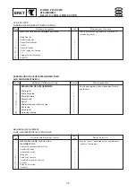
Отзывы: