E
CRANKCASE, CRANKSHAFT AND CAMSHAFT
POWR
2
1
a
YAMAHA
5-35
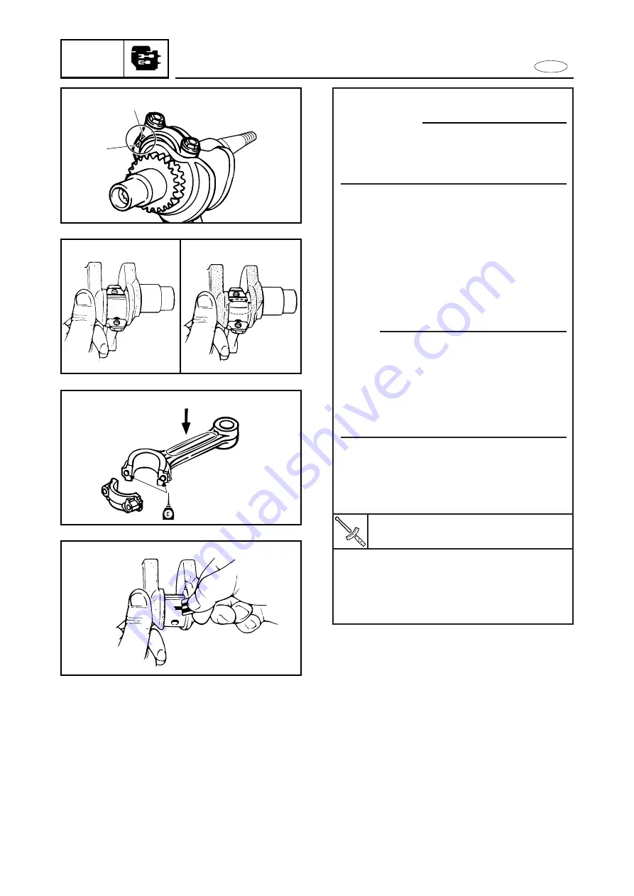
Measurement steps:
c
C
Make sure that the “
Ñ
” connecting rod
mark
1
1
is aligned with the “
D
” cap
mark
2
2
.
8
Clean the cap and big end contact
surface of the connecting rod.
8
Fit the connecting rod to the crank-
shaft.
8
Put a piece of Plastigauge
®
on to the
crank pin.
8
Assemble the connecting rod cap on
to the crank pin.
NOTE:
9
Make sure that the “YAMAHA” mark
a
on the connecting rod faces upwards
on the flywheel rotor ass’y.
9
Do not move the crankshaft until big-
end oil clearance measurement has
been completed.
8
Apply motor oil to the bolts and the
bolt seat.
8
Tighten the bolts to the specified
torque.
8
Remove the connecting rod cap.
8
Measure the width of the com-
pressed Plastigauge
®
on the crank
pin.
Bolt: (connecting rod cap)
12 Nm (1.2 m•kg, 8.7ft•lb)
Содержание F4
Страница 106: ...E FUEL PUMP FUEL 4 7 SERVICE POINTS Fuel pump inspection 1 Inspect 9Diaphragm Damage Replace ...
Страница 296: ...E TRBL ANLS CHAPTER 9 TROUBLE ANALYSIS TROUBLE ANALYSIS 9 1 TROUBLE ANALYSIS CHART 9 1 ...
Страница 306: ......
Страница 307: ...Printed in JAPAN February 1998 2 09 1 n 67D 28197 Z8 C1 F4AMH Printed on recycled paper YAMAHA MOTOR CO LTD ...


