


E
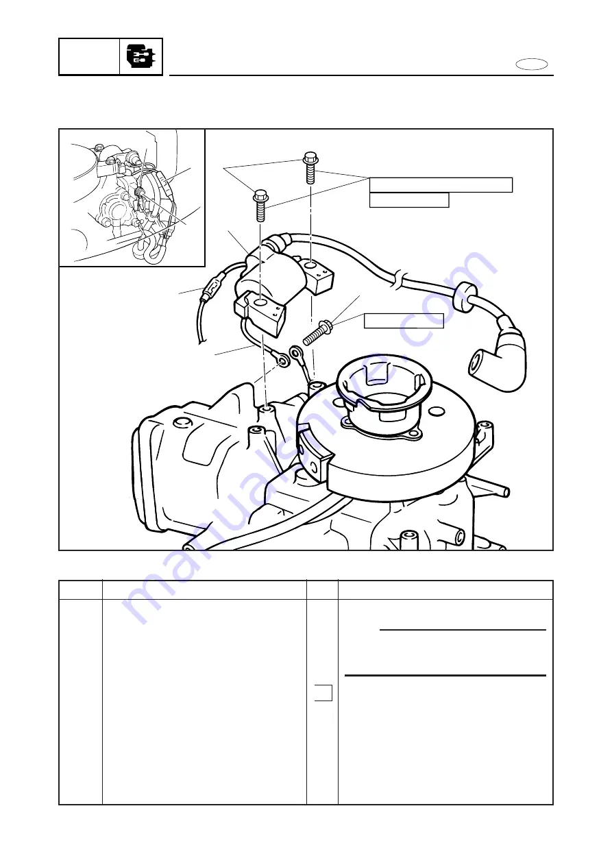
IGNITOR ASS’Y
POWR
IGNITOR ASS’Y
EXPLODED DIAGRAM
4
1
3
2
5
8 Nm (0.8 m•kg, 5.8 ft•lb)
3
1
2
M6 x 25 mm
M6 x 25 mm
5-7
REMOVAL AND INSTALLATION CHART
Step
1
2
3
4
5
Q’ty
1
1
1
2
1
Service points
Follow the left “Step” for removal.
NOTE:
After installing the ignitor ass’y, check the
T.C.I. air gap. Refer to “T.C.I. AIR GAP
ADJUSTMENT” section in chapter 3.
Refer to “INTAKE SYSTEM” section in
Chapter 4.
Refer to “FUEL PUMP” section Chapter 4.
Disconnect
Reverse the removal steps for installation.
Procedure/Part name
IGNITOR ASS’Y REMOVAL
Recoil starter ass’y
Carburetor ass’y
Intake manifold
Fuel pump
Bolt (ground lead)
Ignitor ass’y ground lead
Connector
Bolt with washer (ignitor ass’y)
Ignitor ass’y
Содержание F4
Страница 106: ...E FUEL PUMP FUEL 4 7 SERVICE POINTS Fuel pump inspection 1 Inspect 9Diaphragm Damage Replace ...
Страница 296: ...E TRBL ANLS CHAPTER 9 TROUBLE ANALYSIS TROUBLE ANALYSIS 9 1 TROUBLE ANALYSIS CHART 9 1 ...
Страница 306: ......
Страница 307: ...Printed in JAPAN February 1998 2 09 1 n 67D 28197 Z8 C1 F4AMH Printed on recycled paper YAMAHA MOTOR CO LTD ...