


Chapter 5: Using the EMX
81
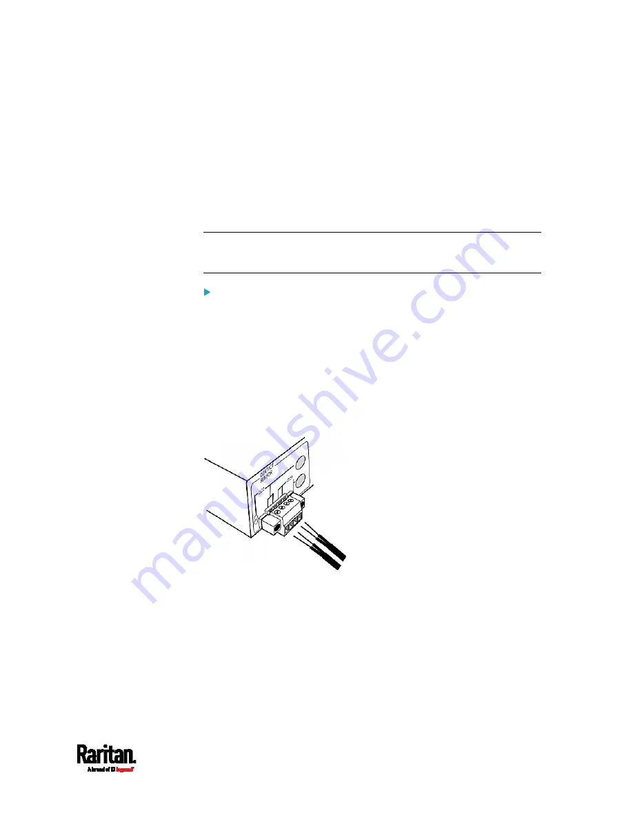
The two termination points to the right are associated with channel 1
(CC1 as indicated in the panel), and the two to the left are associated with
channel 2 (CC2).
With this design, there are two ways to plug discrete detectors/switches:
Connect the discrete detectors/switches while the terminal module
is attached to the EMX.
Connect the discrete detectors/switches while the terminal module
is separated from the EMX.
Important: It is not guaranteed that all third-party
detectors/switches are compatible with the EMX. You need to test
the compatibility after installing them.
To make connections when the terminal module is attached to
the EMX:
1.
Strip the insulation around 12 mm from the end of each wire of
discrete detectors/switches.
2.
Fully insert each wire of both detectors/switches into each
termination point.
Plug both wires of a detector/switch into the two termination
points to the left.
Plug both wires of the other detector/switch into the two
termination points to the right.
Содержание EMX2-111
Страница 69: ...Chapter 4 Connecting External Equipment Optional 57...
Страница 78: ...Chapter 5 Using the EMX 66 EMX2 888...
Страница 442: ...Appendix A Specifications 430 RS 485 Pin signal definition 6 D bi direction al Data 7 8...
Страница 488: ...Appendix E LDAP Configuration Illustration 476 2 The EMX_Admin role is created...
Страница 507: ...Appendix G RADIUS Configuration Illustration 495 Note If your EMX uses PAP then select PAP...
Страница 508: ...Appendix G RADIUS Configuration Illustration 496 10 Select Standard to the left of the dialog and then click Add...
Страница 509: ...Appendix G RADIUS Configuration Illustration 497 11 Select Filter Id from the list of attributes and click Add...
Страница 512: ...Appendix G RADIUS Configuration Illustration 500 14 The new attribute is added Click OK...
Страница 513: ...Appendix G RADIUS Configuration Illustration 501 15 Click Next to continue...


