SD20-G Series
255
current motor is larger than the setting value of Po015, if not, the distance can be increased properly.
2)
Estimate load inertia ratio(Po013)
a)
Preset Po013 as a bigger initial value;
400 of initial value is recommended as preset value, gradually increase till the displayed value in keypad
can be updated with the actual value in the process of identification.
b
)
Increase the rigidity level of the servo drive properly:
Increase the rigidity level (Po010) properly to meet the requirements of inertia identification.
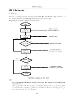
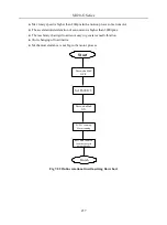
General operation process of offline inertia identification shows as below:
Start
Servo enabled
Po013=200
So-14
Press
key
Display stable?
Finish
No
Yes
Servo enabled,
green light
Current rotational
inertia ratio
Po008=1
Forward/reverse
identification
Increase
Po013
properly
Studied inertia ratio
write to Po013
Fig 7.2.1Offline rotational inertia setting flow chart
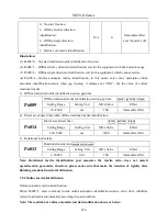
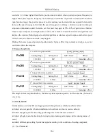
Related Parameters:
1)
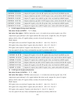
Motion range of offline rotational inertia identification(pulse)
Signal Name
Parameter
Setting Range
Mfr’s value
Content
Motion range
Po015
200~2147483647
—
Approximate value,
One-time identification action
finished in setting pulse range.
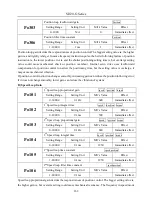
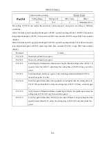
2)
Inertia identification mode selection
Po008
Inertia identification mode selection
speed position torque
Setting Range
Unit
Mfr’s Value
Effect
Содержание SD20-G Series
Страница 35: ...SD20 G Series 35 M3 structure Fig 3 1 5 Servo drive structure 3...
Страница 36: ...SD20 G Series 36 ML3 structure 118 5 5 7 5 93 297 8 223 118 93 0 5 12 5 7 5 4 M4...
Страница 38: ...SD20 G Series 38 M4 structure Approx mass 10 365 kg Fig 3 1 7 Servo drive structure 5...
Страница 39: ...SD20 G Series 39 M5 structure Approx msaa 11 1Kg Fig 3 1 8 Servo drive structure 6...
Страница 40: ...SD20 G Series 40 M6 structure Approx mass 17 4Kg Fig 3 1 9 Servo drive structure 7...
Страница 182: ...SD20 G Series 182 Fig 6 4 44SD20E Cam internal frameworkdiagram...


