SD20-G Series
184
Electronic cam which is provided by SD20 series servo drive, main feature of E-Cam is as the
followings:
Features of E-CAM
Operation
Operate the E-cam in P mode only.
Active
E-CamFunction
PL000.A
PL000.A=0
:
disable E-cam function;
PL000.A=1
:
enable E-cam function and starts to judge the engaged condition;
E-Cam Status
Engage/Stop/Pre-engage
;
Driving shaft
source
● High-speed counter 1
● High-speed counter 2
● Internal position
● Timer axis (add 1 every 0.1ms)
MotionCommand
Actual drive command=E-Cam position command
Data Storage
Address
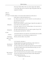
Data array, start from PL200 area;The data of driving shaft ahead, driven shaft
behind.
In communication mode, for instance cam data is X, Y (both X and Y are 32 bits,
value within the range of 32-bit directed number, X input is constant positive)
The address starts from 1200:
Storage address
1200
1201
1202
1203
…
Storage data
X1-low
16-bit
X-high
16-bit
Y1-low
16-bit
Y1-high
16-bit
…
Data Size
Decide by PL015, max 300 points, min 5 points; 6 pages in total, 50 for each page;
Data Format
32-bit signed value(+/-)
E-Cam Output
Digital Output(DO)
:
E-CAM action output; If this DO is ON, it means that the
E-Cam axis is in the setting range;
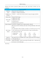
Flow Chart:
Содержание SD20-G Series
Страница 35: ...SD20 G Series 35 M3 structure Fig 3 1 5 Servo drive structure 3...
Страница 36: ...SD20 G Series 36 ML3 structure 118 5 5 7 5 93 297 8 223 118 93 0 5 12 5 7 5 4 M4...
Страница 38: ...SD20 G Series 38 M4 structure Approx mass 10 365 kg Fig 3 1 7 Servo drive structure 5...
Страница 39: ...SD20 G Series 39 M5 structure Approx msaa 11 1Kg Fig 3 1 8 Servo drive structure 6...
Страница 40: ...SD20 G Series 40 M6 structure Approx mass 17 4Kg Fig 3 1 9 Servo drive structure 7...
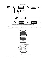
Страница 182: ...SD20 G Series 182 Fig 6 4 44SD20E Cam internal frameworkdiagram...


